


MX-M700N ADJUSTMENTS 6 – 26
(Leading edge image loss/void area adjustment)
1)
Set the adjustment values for leading edge image loss and
leading edge void as follows:
(Standard setting)
Leading edge image loss: 1.5 mm (LEAD:15)
Leading edge void: 3.5mm (DENA:35)
* Set the adjustment value for (LEAD) to 15 by entering "15"
into the (LEAD) adjustment value field and then pressing the
P key.
* Set the adjustment value for (DENA) to 35 by entering "35"
into the (DENA) adjustment value field and then pressing the
P key.
2)
Make a copy at 100% magnification by entering "100" into the
(MAGNIFICATION) field and then pressing the Start key, and
check the leading edge void area and image loss.
If the leading edge image loss and void area are not at accept-
able levels, do the following steps.
* If the leading edge void area is not 3.5 mm:
Repeat the process of changing the (RRCB) adjustment
value and then pressing the Start key until attaining an
acceptable level.
(The change according to the one step of the adjustment
value is 0.1mm.)
* If the leading edge image loss is not 1.5mm:
Repeat the process of changing the (RRCA) adjustment
value, in steps of 0.1 mm, and then pressing the Start key
until attaining an acceptable level.
(The adjustment value should be changed in steps of
0.2mm.)
Repeat the above adjustments until acceptable results are
obtained.
(Trailing edge void area adjustment)
1)
Make a copy at 100% magnification by entering "100" into the
(MAGNIFICATION) field and then pressing the Start key, and
check the trailing edge void area.
(Standard setting) Trailing edge void area: 3.5 mm
If the trailing edge void area is not at an acceptable level, do
the following steps.
2)
Repeat the process of changing the (TRAIL EDGE) adjust-
ment value and then pressing the Start key until attaining an
acceptable level.
Repeat the above adjustments until acceptable results are
obtained.
(Front/rear frame direction image loss adjustment)
1)
Set the (SIDE) adjustment value to 20 by entering "20" into the
(SIDE) adjustment value field and then pressing the P key.
Note that changing this adjustment value shifts the image posi-
tion in the front/rear frame direction.
(Front/rear frame direction void area)
1)
Make a copy at 100% magnification by entering "100" into the
(MAGNIFICATION) field and then pressing the Start key, and
check the front/rear frame direction void area.
(Standard settings)
Front frame side void area = 3.5 mm, rear frame side void area
= 3.5 mm, sum of front/rear frame direction void area = 7.0
mm.
If the front/rear frame direction void area is not at an accept-
able level, do the following steps.
2)
Repeat the process of changing the (FRONT/REAR) adjust-
ment value and then pressing the Start key until attaining an
acceptable level.
Repeat the above adjustments until acceptable results are
obtained.
NOTE: If the front and rear frame side void areas are not equal,
adjust the image off-center position using Simulation 50-5.
SIDE2-ADJ
Offset (adjustment) of the
RRCB setting during rear print.
1 – 99
50
(Image loss set value)
5
LEAD
LEAD Lead edge image loss
set value
0 – 99
15
6
SIDE
Side image loss set
20
(Void set value)
7
LEAD_EDGE
(DENA)
Lead edge void set value
0 – 99
35
8
TRAIL_EDGE
(DENB)
Rear edge void adjustment
value
9
FRONT/REAR
Front/Rear void adjustment
value
Item
Content
Setting
range
Default
10
20
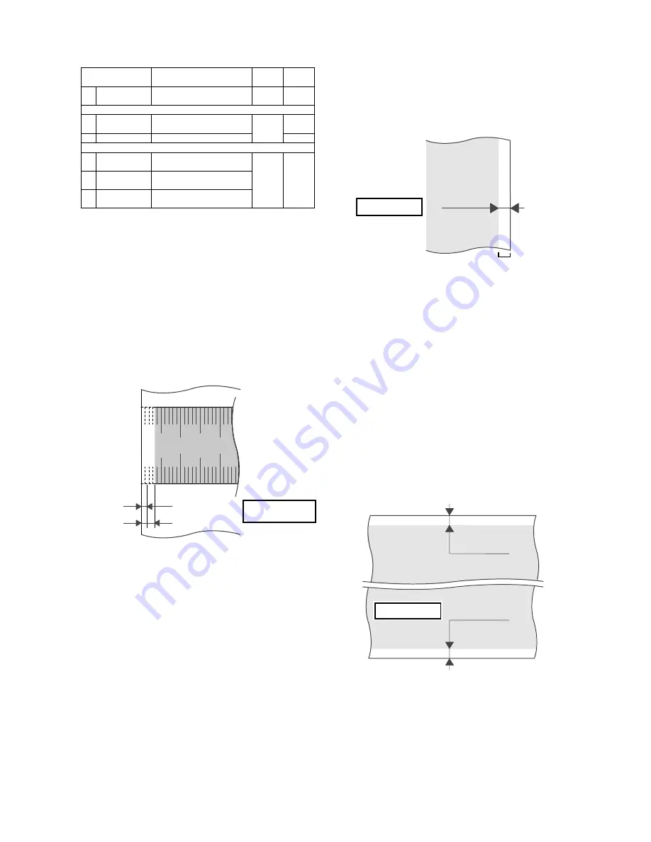
Image loss (LIL)
LIL = 1.5 mm
LV = 3.5 mm
Image area
Papar lead edge
Void (LV)
No Image
Papar tail edge
TV
= 3.5 mm
No Image
Void (TV)
FV+RV= 7.0 mm
No Image
No Image
Void (FV)
Void (RV)