


MX-M700N SIMULATION 7 – 47
4)
The input value is saved by pressing the [START] key
49
49-1
Purpose
Setting/update
Function (Purpose)
Firmware updating
Section
—
Operation/Procedure
1)
Before proceeding to the sim.49-1 screen, insert the USB
memory to the main unit.
* File and folder of the USB memory are displayed. (When the
foldername is longer than 34 characters, it is not completely
displayed.)
* If the USB memory is not inserted, "INSERT A USB MEM-
ORY DEVICE CONTAINING MFP FIRMWARE, PLEASE
USE FAT (12/16) FORMAT" is displayed.
* Non compliant to FAT32. If it's inserted, "CAN NOT SUP-
PORT FAT32. PLEASE USE FAT (12/16) FORMAT" is dis-
played.
2)
Enter the file/folder number of firmware that tries to be updated
with 10-key, and press [START] key.
3)
If selecting the file, "FIRMWARE UPDATE.. ARE YOU SURE
?" is displayed. ([1]: execute, [2]: get back)
* If the operation is normally completed, "COMPLEATE" is
displayed. When the error occurs, "ERROR" is displayed.
50
50-1
Purpose
Adjustment
Function (Purpose)
Used to adjust the copy image position and
the void area (image loss) adjustment on
print paper in the copy mode. (The similar
adjustment can be performed with SIM 50-
5 and 50-2 (Simplified method).) (Docu-
ment table mode)
Section
—
Operation/Procedure
(Leading edge image loss/void area adjustment)
1)
Set the adjustment values for leading edge image loss and
leading edge void as follows:
(Standard set value)
Lead edge image loss: 1.5mm (LEDA: 15)/Paper lead edge
void: 3.5mm (DENA: 35)
* Set LEAD to 15. (Enter 15 as the adjustment value of LEAD,
and press [P] key.) (0.1mm/step)
* Set DENA to 35. (Enter 35 as the adjustment value of
DENA, and press [P] key.) (0.1mm/step)
2)
Make a copy at the normal ratio (100%) and check the lead
edge void area and the image loss. (Enter 100 as the set value
of the copy magnification ratio (MAGNIFICATION), and press
[START] key.)
3)
If an acceptable result is not obtained, do the following steps.
* If the leading edge void area is not 3.5 mm:
Change the adjustment value of RRCB and perform the
adjustment. (Change the adjustment value of RRCB and
press [START] key.) (1msec/step)
* If the lead edge image loss is not 1.5mm:
Change the adjustment value of RRCA and perform the
adjustment. (Change the adjustment value of RRCA and
press [START] key.)
(The adjustment value should be changed in steps of
0.2mm.)
(Trailing edge void area adjustment)
Adjust so that the rear edge void area is 3.5mm. (Change the
adjustment value of TRAIL EDGE, and press [START] key.)
(Front/rear frame direction image loss adjustment)
Set the (SIDE) adjustment value to 20 by entering "20" into the
(SIDE) adjustment value field and then pressing the [P] key.
Note that changing this adjustment value shifts the image position
in the front/rear frame direction.
(Front/rear frame direction void area)
Set the adjustment value of SIDE to 20. (Enter 20 as the adjust-
ment value of SIDE, and press [P] key.)
Adjust so that the total of the front/rear direction void areas is
7.0mm. (Change the adjustment values of FRONT/REAR, and
press [START] key.)
Front frame void area = 3.5mm Rear frame void area = 3.5mm
If, as shown above, the front and the rear void areas are not even,
use SIM 50-5 to adjust the image off-center position.
NOTE: When [P] key is pressed after entering an adjustment value
in this simulation, the adjustment value is set. When
[START] key is pressed, the adjustment value is set and
copying is performed.
0
SIMULATION 48-5
MOTOR SPEED ADJUSTMENT. SELECT 0-4, AND PRESS START.
0.MIR(220)
50
1.MIR(110)
50
2.SPF(360)
50
3.SPF(220)
50
4.SPF(110)
50
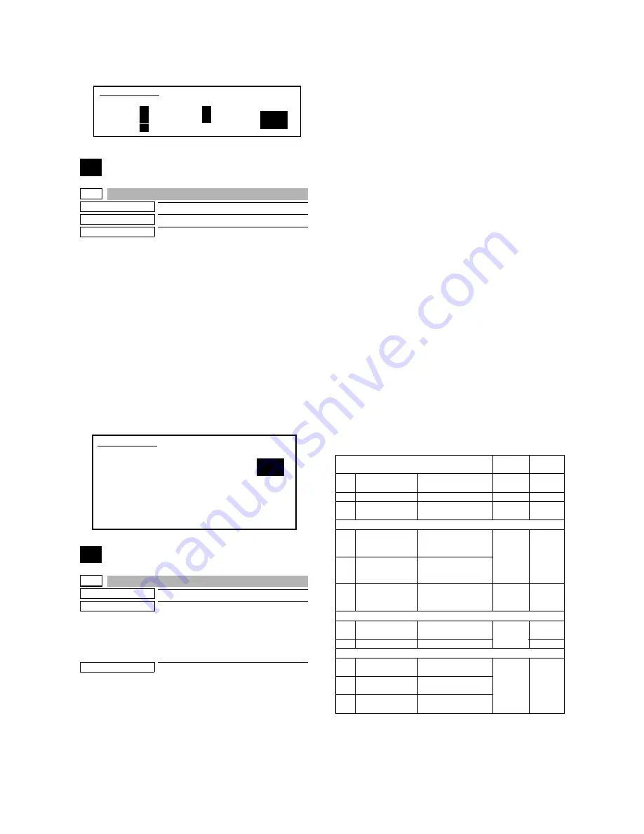
SIMULATION 49-1
FIRMWARE UPDATE.
SELECT FIRMUP FILE, AND PRESS START.
1. FILE1.sfu
2. FILE2.sfu
3. FILE3.sfu
.
.
19. >>NEXT Page
0
Item
Setting
range
Default
0
TRAY SELECT
Paper feed tray
selection
1 - 6
-
1
COPY START
Copy START (Default)
-
-
2
MAGNIFICATION
Print magnification
ratio
25 -
400%
-
(Lead edge adjustment value)
3
RRCA
Document scan start
position adjustment
value
0 - 99
50
4
RRCB
Resist roller clutch ON
timing adjustment
value
10
SIDE2 ADJ.
Correction value for
RRCB in the back
surface print mode
1 - 99
50
(Image loss set value)
5
LEAD
LEAD Lead edge
image loss set value
0 - 99
15
6
SIDE
Side image loss set
20
(Void set value)
7
LEAD_EDGE
(DENA)
Lead edge void set
value
0 - 99
35
8
TRAIL_EDGE
(DENB)
Rear edge void
adjustment value
9
FRONT/REAR
Front/Rear void
adjustment value