


Manual – MOVIPRO® SDC with DeviceNet Interface
133
11
MOVIPRO
®
SDC error list
Service
11.3 MOVIPRO
®
SDC error list
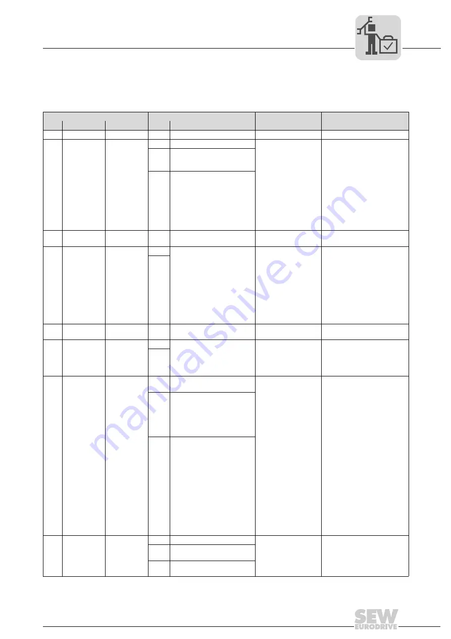
The factory set error response is listed in the "Response (P)" column. "(P)" means that
the response can be set with parameter
P83_error response
.
Error
Suberror
Code Designation
Response (P) Code Designation
Possible cause
Measure
00
No error
01
Overcurrent
Immediate dis-
connection
0
Output stage
•
Short circuit at
output
•
Motor too large
•
Faulty output stage
•
Ramp limit is
deactivated and set
ramp time is too
short
•
Braking resistance
value too low
•
Short circuit in the
braking resistor
circuit
•
Rectify the short circuit
•
Connect a smaller motor
•
Consult SEW Service if the
output stage is defective.
•
Extend the ramp time
•
Check technical data of
braking resistor
•
Check the supply cable of
the braking resistor
1
V
CE
monitoring or undervolt-
age monitoring of the unit
driver
5
Inverter remains in hardware
current limit
03
Ground fault
Immediate dis-
connection
0
04
Brake chopper
Immediate dis-
connection
0
DC link voltage too high in 4Q
operation
•
Too much
regenerative power
•
Braking resistor
circuit interrupted
•
Short circuit in the
braking resistor
circuit
•
Brake resistance
too high
•
Brake chopper
defective
•
Extend deceleration ramps
•
Check supply cable to
braking resistor
•
Check technical data of
braking resistor
•
Replace MOVIPRO
®
if the
brake chopper is defective
1
06
Mains phase
failure
Immediate dis-
connection
0
DC link voltage periodically too
low
Phase failure
Check the line cable
07
DC link over-
voltage
Immediate dis-
connection
0
DC link voltage too high in 2Q
operation
DC link voltage too high •
Extend deceleration ramps
•
Check supply cable to the
braking resistor
•
Check technical data of
braking resistor
1
08
Speed moni-
toring
Immediate dis-
connection (P)
0
Inverter in current limit or in slip
limit
•
Speed/current
controller (in VFC
operating mode
without encoder)
operating at setting
limit due to
mechanical
overload or phase
fault in the power
system or motor.
•
Encoder not
connected correctly
or incorrect
direction of rotation
•
n
max
is exceeded
during torque
control.
•
In operating mode
VFC: Output
frequency > 150 Hz
•
In operating mode
V/f: Output
frequency > 600 Hz
•
Reduce load
•
Increase delay time setting
(
P501 or P503
).
•
Check encoder connection,
swap A/A and B/B pairs if
necessary
•
Check encoder voltage
supply
•
Check current limitation
•
Extend ramps if necessary
•
Check motor cable and
motor
•
Check mains phases
3
"Actual speed" system limit
exceeded.
Speed difference between
ramp setpoint and actual value
for 2 × ramp time higher than
expected slip
4
Maximum rotating field speed
exceeded
Maximum rotating field fre-
quency (with VFC max 150 Hz
and V/f max 600 Hz) exceeded
09
Startup
Immediate dis-
connection
0
Startup missing
Inverter has not been
started up for the
selected operating
mode.
Perform startup for the required
operating mode.
1
Wrong operating mode
selected
2
Wrong encoder type or defec-
tive encoder card


