13-Survey & Map Mode
Noggin
94
13.3 Noggin Setup
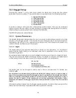
Pressing the number 1 on the main menu selects the Setup item. Setup lists the various
parameters that can be edited. These parameters are organized under the following headings:
1 - System Parameters
2 - Cart Parameters
3 - Line Parameters
4 - Grid Parameters
5 – GPS Parameters
6 – Set Defaults
To select a setting to edit, press the corresponding number button. Then use the numbered
buttons to select the new setting. It is also possible to change all the settings back to the factory
default settings by pressing the 6 button (labelled Set Defaults).
The SETUP options are outlined below.
13.3.1 System Parameters
The System Parameters settings allow the user to view and modify settings specific to the data
collection of the Noggin system. This includes the type of Noggin system, the desired depth of
investigation, the velocity of the material being surveyed, the units of depth and position, the
number of stacks and the amount of linear gain.
13.3.1.1 Depth
The depth setting is how deep the radar will try to probe in to the subsurface. It is important to
realize that the depth setting is an estimated value that is dependent on the velocity of the
material being probed.
Ground penetrating radar systems record the
time
for a radio wave to travel to a target and back.
They do not measure the depth to that target directly. The depth to a target is calculated based
on the velocity at which the wave travels to the target and back. It is calculated as:
D = V x T/2
Where
D is Depth (m)
V is Velocity (m/ns)
T is Two-way travel time (ns)
The Depth units can be changed to meters, feet or time in nanoseconds. For details, see
13.3.1.3: p.95
.
It is important to remember that just because the Depth setting is set to a certain value, it
does not necessarily mean that the Noggin is able to penetrate to that depth and collect
data. For example, if the Depth setting is 5 meters but the material penetration is only 3
meters the last 2 meters of the image will not contain subsurface information. Some
materials will absorb the Noggin signal and limit penetration to less than the selected
depth.
If the depth setting is deeper than the Noggin signals penetrate, the data in the lower part of the
data screen will look blank or speckled rather than signal with continuity.
Содержание Noggin 100
Страница 1: ...User s Guide Copyright 2012 Sensors Software Inc 2011 00022 02 Noggin ...
Страница 2: ......
Страница 4: ......
Страница 8: ......
Страница 17: ...Noggin 2 Noggin Components 3 Figure 2 3 Noggin 100 components ...
Страница 156: ...Appendix D Instrument Interference Noggin D 2 ...
Страница 158: ...Appendix E Safety Around Explosive Devices Noggin E 2 ...
Страница 162: ...Noggin G 4 ...


