


U.2.33
Date Code 20020501
User’s Guide
SEL-421/SEL-421-1 Relay
Installation
Connection
Connection
CAUTION:
Insufficiently rated
insulation can deteriorate under
abnormal operating conditions and
cause equipment damage. For
external circuits, use wiring of
sufficiently rated insulation that will
not break down under abnormal
operating conditions.
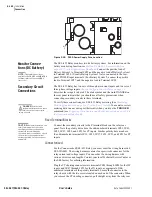
The SEL-421 Relay is available in many different configurations depending
on the number and type of control inputs, control outputs, and analog input
termination you specified at ordering. This subsection presents a
representative sample of relay rear-panel configurations and the connections
to these rear panels. Only horizontal chassis are shown; rear panels of vertical
chassis are identical to horizontal chassis rear panels for each of the 3U, 4U,
and 5U sizes.
When connecting the SEL-421 Relay, refer to your company plan for wire
routing and wire management. Be sure to use wire that is appropriate for your
installation with an insulation rating of at least 90°C.
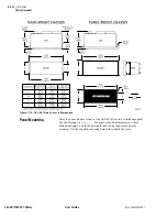
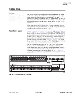
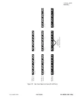
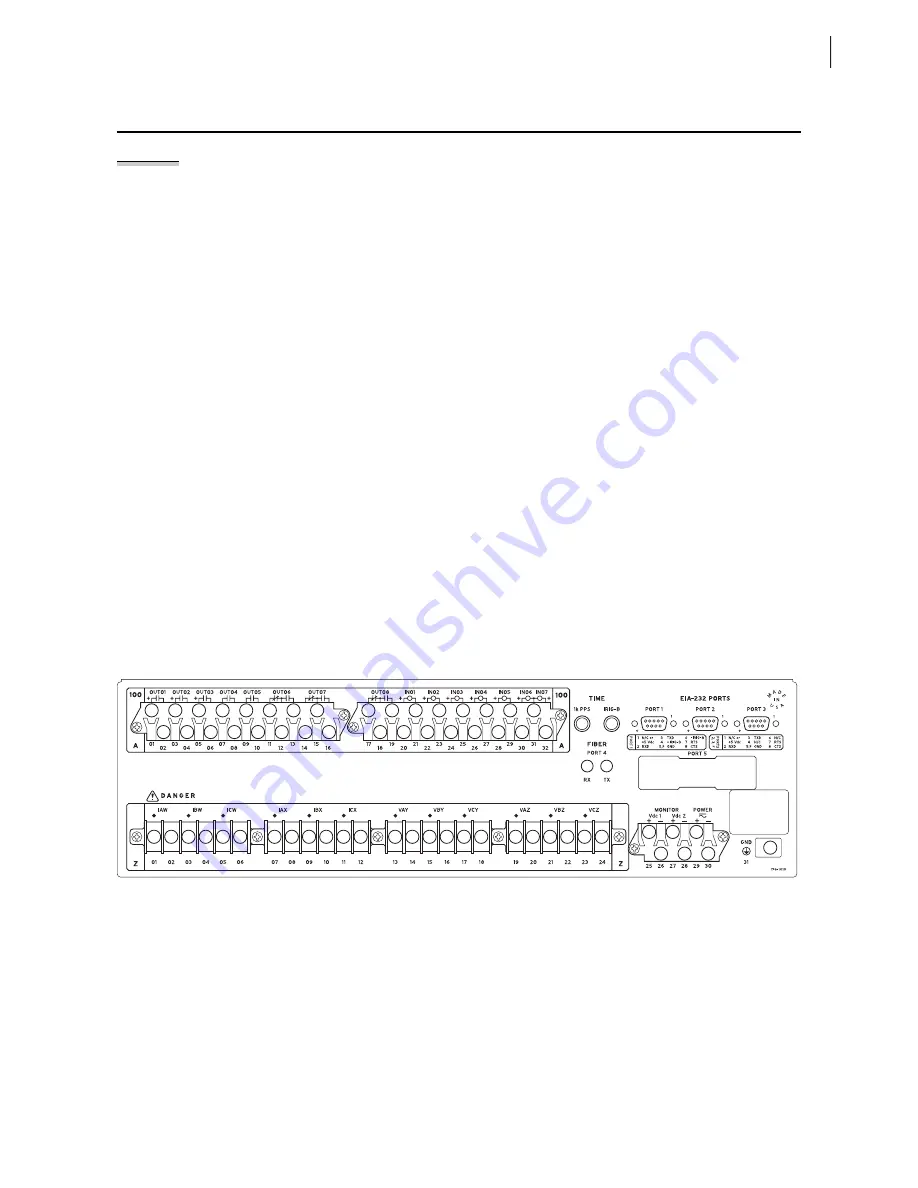
Rear-Panel Layout
, and
, and
show some of the available SEL-421
Relay rear panels. All relay versions have screw terminal connectors for I/O,
power, and battery monitor. You can order the relay with fixed terminal blocks
for the CT and PT connections, or you can order SEL Connectorized rear-
panel configurations that feature plug-in/plug-out PT connectors and shorting
CT connectors for relay analog inputs.
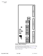
shows the
Connectorized 3U horizontal configuration of the SEL-421 Relay. For clarity,
the figures do not show a communications card installed in PORT 5.
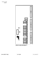
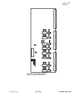
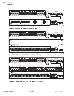
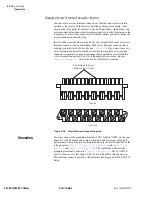
The screw terminal connections for the INT1 and the INT6 I/O interface
boards are the same. The INT5 I/O interface board has control output
terminals grouped in threes, with the fourth terminal as a blank additional
separator (terminals 4, 8, 12, 16, 20, 24, 28, and 32). For more information on
the main board control inputs and control outputs, see
. For more information on the I/O interface board control inputs and
control outputs, see
I/O Interface Board Jumpers on page 2.21
.
Figure 2.20
3U Rear Panel, SEL-421 Relay.
i3359a
Содержание SEL-421
Страница 8: ...This page intentionally left blank ...
Страница 30: ...This page intentionally left blank ...
Страница 110: ...This page intentionally left blank ...
Страница 204: ...This page intentionally left blank ...
Страница 284: ...This page intentionally left blank ...
Страница 286: ...This page intentionally left blank ...


