


U.2.15
Date Code 20020501
User’s Guide
SEL-421/SEL-421-1 Relay
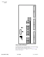
Installation
Plug-In Boards
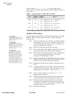
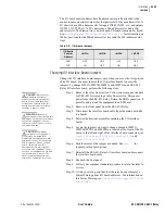
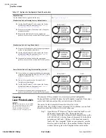
Step 13. Apply power. Enter Access Level 2 (
Changes on page U.4.15 in the User’s Guide
). Issue the
STA
command and answer
Y<Enter>
to accept the new hardware
configuration (see
STATUS on page R.8.45 in the Reference
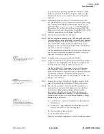
Step 14. Inspect the relay targets to confirm that the relay reads the
added I/O interface board(s). You can see the new control
inputs in the target listings by using a terminal, the SEL-5030
AC
SEL
ERATOR®
Software Program, and the front panel. Use a
communications terminal to issue the commands
TAR
OUT201<Enter>
(for the 200-addresses slot) or
TAR
OUT301<Enter>
(for the 300-addresses slot). Alternatively,
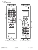
from the front panel MAIN MENU, select RELAY
ELEMENTS, press the down pushbutton to go to ROW 94 (for
the 200-addresses slot) or ROW 97 (for the 300-addresses slot).
Step 15. Follow your company standard procedure to return the relay to
service.
Communications
Card
You can add other communications protocols to the SEL-421 Relay by
inserting a communications card in the rear-panel PORT 5 slot. Ethernet
communication is possible by adding the SEL-2701 Ethernet
Communications Processor card. The SEL-2701 is an Ethernet device for
industrial installations that handles data traffic between the SEL-421 Relay
and a LAN (local area network).
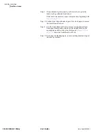
Installing the Communications Card
To install a communications card in an SEL-421 Relay, perform the following
steps. If your communications card is already installed, skip the following
steps and perform the Initial Checkout procedures for your communications
card.
Step 1. Remove the relay from service. Follow your company standard
for removing a relay from service. Disconnect power from the
SEL-421 Relay. Retain the GND connection, if possible, and
ground the equipment to an ESD mat.
Step 2. Remove the front panel from the SEL-421 Relay.
Step 3. Disconnect the power, interface board cable(s), and input board
analog cable from the main board (the top board).
Step 4. Remove the cover from the PORT 5 slot.
Step 5. Remove the screw terminal connectors. Loosen the attachment
screws at each end of the 100-addresses screw terminal
connectors. Pull straight back to remove.
Step 6. Remove rear-panel EIA-232 Ports mating connectors. Unscrew
the keeper screws and disconnect any serial cables connected to
the Port 1, Port 2, and Port 3 rear-panel receptacles.
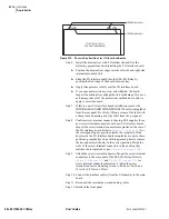
Step 7. Pull out the drawout tray containing the main board.
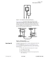
Step 8. Insert the communications card 80-pin connector into the 80-
pin receptacle on the underside of the host main board, taking
the following precautions:
➢
Ensure the connector pins line up with the guide holes
on the host main board.
DANGER:
Disconnect or
de-energize all external
connections before opening this
device. Contact with hazardous
voltages and currents inside this
device can cause electrical shock
resulting in injury or death.
!
WARNING:
Have only
qualified personnel service this
equipment. If you are not qualified to
service this equipment, you can
injure yourself or others, or cause
equipment damage.
!
CAUTION:
Equipment
components are sensitive to
electrostatic discharge (ESD).
Undetectable permanent damage
can result if you do not use proper
ESD procedures. Ground yourself,
your work surface, and this
equipment before removing any
cover from this equipment. If your
facility is not equipped to work with
these components, contact SEL
about returning this device and
related SEL equipment for service.
!
Содержание SEL-421
Страница 8: ...This page intentionally left blank ...
Страница 30: ...This page intentionally left blank ...
Страница 110: ...This page intentionally left blank ...
Страница 204: ...This page intentionally left blank ...
Страница 284: ...This page intentionally left blank ...
Страница 286: ...This page intentionally left blank ...


