


U.6.25
Date Code 20020501
User’s Guide
SEL-421/SEL-421-1 Relay
Testing and Troubleshooting
Checking Relay Operation
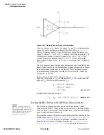
Negative-Sequence Overcurrent Elements
The SEL-421 Relay negative-sequence overcurrent elements compare a
negative-sequence calculation of the three-phase secondary inputs with the
corresponding negative-sequence overcurrent element pickup setting. The
relay makes this negative-sequence calculation (assuming ABC rotation):
3I
2
= A-phase + B-phase (shifted by –120°) + C-phase (shifted by 120°)
The relay asserts negative-sequence overcurrent elements when the 3I
2
calculation exceeds the corresponding negative-sequence current pickup
setting. If balanced currents are applied to the relay, the relay reads 3I
2
»
0
(load conditions) and does not pick up the negative-sequence overcurrent
elements.
For testing, apply current to a single phase of the relay, causing the negative-
sequence overcurrent elements to operate. For example, assume 1 A of current
on A-phase and zero current input on the B-phase and C-phase:
3I
2
= 1 A + 0 (shifted –120°) + 0 (shifted 120°) = 1 A (a simulated ground
fault condition)
Ground Overcurrent Elements
The SEL-421 Relay ground overcurrent elements compare a residual ground
calculation of the three-phase inputs with the residual overcurrent setting. The
relay makes this residual current calculation:
3I
0
= A-phase + B-phase + C-phase
The relay asserts ground overcurrent elements when the 3I
0
calculation
exceeds the ground current element pickup setting. If balanced currents are
applied to the relay, the relay reads 3I
0
= 0 (load conditions) because the
currents cancel in the calculation; the relay does not pick up the ground
overcurrent elements.
For testing, apply current to a single phase of the relay, causing the residual
overcurrent elements to operate. For example, assume 1 A of current on A-
phase and zero current input on B-phase and C-phase:
3I
0
= 1 A + 0 + 0 = 1 A (a simulated ground fault condition)
Checking the Negative-Sequence
Instantaneous Overcurrent Element, 50Q1
NOTE:
As you perform this test,
other protection elements can assert.
This causes the relay to assert other
targets and possibly close control
outputs. Be sure to isolate the relay
from the power system to avoid
unexpected system effects.
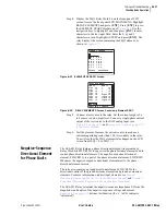
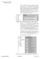
The procedure in the following steps tests the 50Q1 negative-sequence
overcurrent element. Use a similar procedure to test other overcurrent
elements.
This example assumes that you have successfully established communication
with the relay; see
Making an EIA-232 Serial Port Connection on page U.4.6
for a step-by-step procedure. In addition, you must be
familiar with relay access levels and passwords. See
Passwords on page U.4.8 in the User’s Guide
to change the default access
level passwords and enter higher relay access levels. You should be familiar
with the
AC
SEL
ERATOR
software; see
Section 3: PC Software in the User’s
.
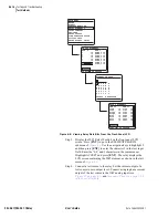
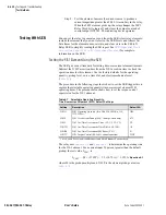
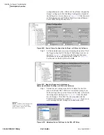
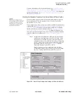
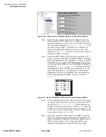
Step 1. Configure the relay. Start the
AC
SEL
ERATOR
software and read
the present configuration in the SEL-421 Relay. On the Settings
menu, click Read. The relay sends all settings and
Содержание SEL-421
Страница 8: ...This page intentionally left blank ...
Страница 30: ...This page intentionally left blank ...
Страница 110: ...This page intentionally left blank ...
Страница 204: ...This page intentionally left blank ...
Страница 284: ...This page intentionally left blank ...
Страница 286: ...This page intentionally left blank ...


