background image

Rostock Max Assembly Guide 


20 


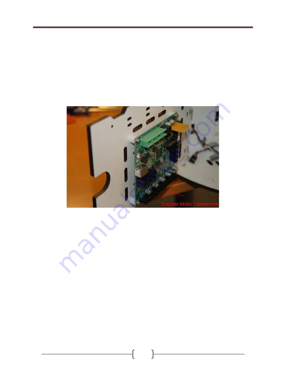
7.4 – If you’re installing on the inside of the mounting plate, orient the RAMBo such that the 

stepper motor connectors are towards the bottom of the mounting plate.  This allows the USB cable to 
exit through the finger notch on the door. 


7.5 - If you’re mounting to the outside, orient the board such that the stepper motor connectors 

are close to the top of the mounting plate. 


7.6 - The SeeMeCNC assembly video shows using one plastic spacer on either side of the board.  

I chose to install the board with both spacers stacked behind the circuit board.  Take care not to over-
tighten the screws or you could crack the circuit board. 


Figure 26 - Mounting the RAMBo 


Содержание Rostock Max

Страница 1: ...s Forceps these are VERY handy and will make your life easier in a number of the assembly steps They look like this You can purchase these online from Amazon for as little as 3 50 for a set of two I would recommend getting the ones with a slight curve to the jaws Wire Strippers Wire Cutters Metric Tape Measure or Meter Stick A Small File you may wish to get both a fine and coarse file This is need...

Страница 2: ...ve the missing components on their way to you in no time The laser cut components in the Rostock Max kit are held in place with masking tape to ensure that they re not damaged in transit The simplest way to remove these parts from the scrap material is to use a razor blade to cut the tape around the perimeter of the part Each laser cut part also has a protective film on it that must be removed Thi...

Страница 3: ...Rostock Max Assembly Guide 3 Figure 1 The parts for the Rostock MAX printer ...

Страница 4: ...ve been engraved through the Melamine surface Popping them out is easy using the point of a razor knife It exposes the softer inner material of the Melamine and allows flat head screws to create their own counter sink by the pressure they apply as they re tightened down 1 3 Install the six feet to the bottom face of the base plate P N 69355 Figure 3 Plastic parts that make up the feet for the mach...

Страница 5: ...n the _other_ side Installing them as shown in the photo will prevent the soft rubber caps from fitting properly Figure 4 First two feet mounted 1 5 This is what the six feet should look like when installed in their proper location Figure 5 All six mounted with rubber caps installed 1 6 The white caps just fit over the black plastic feet Makes for a great non slip assembly ...

Страница 6: ... Max Assembly Guide 6 1 7 Install the Tri Supports P N 86352 T Slot Supports P N 68377 and Motor Mount P N 68364 Figure 6 Tri Support and T Slot Support Figure 7 Dry fitting the T Slot and Tri Support together ...

Страница 7: ...nk rings on the Tri Support and install a pair of 6 32 Nylon lock nuts into the notches in the T Slot Support as shown below Figure 8 Lock nut installed in the T Slot Support 1 9 Take two 6 32 1 long flat head machine screws and attach the T Slot Support to the Tri Support as shown Make sure that the counter sink rings are facing out when you assemble the parts Figure 9 Tri Support assembled ...

Страница 8: ...oors in place The connectors for the X and Y axis motors can be connected directly to the wires on the stepper motors but the Z axis requires a short extension to reach the electronics bay Figure 10 Motor Mount attached 1 12 Install Tri Support assemblies into the base plate Before mounting in the base install the 6 32 nylon locknuts doing them at this stage is much simpler than when the assembly ...

Страница 9: ...blies are installed Install first two as shown Figure 11 Two Supports installed 1 14 Install Power supply mount in third support note that it s a simple friction fit at this point It gets attached to the base when the whole assembly is installed Figure 12 Power Supply Bracket in place ...

Страница 10: ...ng the top to the base 1 17 Install Cover Brackets P N 68361 The brackets that are installed to either side of the power supply need to have threads cut in them Figure 14 Cutting threads in the bracket 1 18 To cut the threads in the bracket take a 10 32 socket head cap screw and carefully thread them into the holes at the top bottom of two brackets This is where the Nylon thumb screws will be inst...

Страница 11: ...ectronics Door installed 1 20 Install Electronics Mount P N 68358 and Support Panel P N 68357 Refer to Fig 15 above for the location of the Electronics Panel The door pin fits into the hole located next to the X axis T Slot mount 1 21 Install the Support Panel as shown the door pin fits into the hole next to the Y axis T Slot mount Figure 16 Support Door installation ...

Страница 12: ...Orient the top so that the Z axis is straight across from the Electronics Panel Figure 17 Base Top Orientation 1 23 It can be difficult to get all the tabs aligned with the slots in the top of the machine I recommend that you choose a point get a few tabs inserted in the base slots and then loosely install a few of the 6 32 1 flat head screws around that location This will allow you to work your w...

Страница 13: ...asher on it Tighten it down until the tiny prongs have penetrated fully into the Melamine If you re building an Acrylic version flatten the prongs with your needle nosed pliers and tape the t nuts in place with a bit of scotch or other tape 2 2 Attach the heated bed to Mount Bed Insulator P N 68335 using eight 4 4 socket head screws Set a small plastic spacer over each of the mounting holes that y...

Страница 14: ...t pulley is made from aluminum and can be stripped out easily Tighten both screws equally Figure 19 Belt Pulley Installed 3 2 Note that if the set screws in your kit are as large as those shown in Fig 19 you ll need to install the pulley after you ve installed the stepper motor in the motor mount The set screws won t clear the opening in the motor mount ...

Страница 15: ...ics must be installed on the inside of the electronics mounting plate If the electronics are installed on the outside face of the electronics mounting plate you ll need to test fit each stepper motor in order to determine which ones will require an extension cable 4 2 Using the included wire the extension wiring pattern goes like this Stepper Wire Extension Wire Red Red Black Black Green Green Blu...

Страница 16: ... by a small triangle pointer that points to the end of the connector Fig 20 below shows a 2 pin connector with this pin 1 arrow The four pin stepper connectors have the same style indicator Figure 20 Pin 1 Indicating Arrow Figure 21 Stepper motor with connector installed ...

Страница 17: ...n easily strip out the holes on the stepper motors 5 3 There are access holes directly across from each of the four stepper motor mounting holes they are there to allow you to install the screws on each motor A longer than normal screwdriver may help here 5 4 At this point you ll want to install the belt pulley on each motor if you haven t done so already Make sure that when you install the pulley...

Страница 18: ...lat tip screwdriver for this Figure 23 Power Supply Installation 6 2 Insert the power supply with the wiring end pointing toward the center of the machine and rotate to the left to set it into position 6 3 Do not tighten all four screws until you have them all started otherwise you ll only be able to place three of the four I recommend starting the two screws closest to the Tri Support that the po...

Страница 19: ...stallation uses four 4 40 x socket head cap screws four 4 40 t nuts four 4 flat washers and eight of the small plastic spacers 7 3 If you re building the Melamine version don t fold back the prongs on the T nuts Instead take one of the mounting screws and a 4 washer and use that to set the T nut into the mounting panel as shown below Figure 24 Installing the T Nuts front side Figure 25 Installing ...

Страница 20: ...finger notch on the door 7 5 If you re mounting to the outside orient the board such that the stepper motor connectors are close to the top of the mounting plate 7 6 The SeeMeCNC assembly video shows using one plastic spacer on either side of the board I chose to install the board with both spacers stacked behind the circuit board Take care not to over tighten the screws or you could crack the cir...

Страница 21: ...cap screws and 12 each of the 1 4 20 t slot nuts Figure 27 T Slot Hardware 8 2 When installing the fasteners orient the t slot nut with the boss or protruding thread area facing the inside of the T Slot rail as shown below Figure 28 Orientation of T Nut Boss 8 3 Install four screw nut pairs in each rail location as shown below Figure 29 T Slot Nuts Installed ...

Страница 22: ...ully slide the three rails over the t slot nuts the fit may be a bit tight if you don t have the t nuts loose enough Slide rail down to meet the scribe line marked on the panel Figure 30 Rail Installed to Alignment Line 8 6 Tighten screws only enough to hold the rail in place this will be adjusted and tightened up later in the build process Figure 31 All Three Rails Installed ...

Страница 23: ...P N 68370 9 2 Insert the remaining 1 4 20 button head screws as shown in the photo below 9 3 Note that you may want to keep the writing facing in in order to make sure the horizontal alignment mark is visible Figure 32 Button Head Screws Installed 9 4 Assemble each Idler Mount as shown below and then attach them to the top plate as shown in Fig 34 Figure 33 Idler Mount Assembled ...

Страница 24: ...t Plate P N 68368 as shown below Figure 34 Idler Mount Installed 9 6 Note that the mounting screw shown in Fig 34 is a 4 40 1 1 4 machine screw that is threaded into a 4 40 T Nut that s installed on the underside face of the Top Support Plate Figure 35 Mounting Screw and T Nut ...

Страница 25: ...pport Plate 10 1 Attach the Top Support Plate to the mounting rails Finger tighten the button head screws after you ve got the Top Support Plate installed The Idler Brackets get a final adjustment and tightening later Figure 36 Top Support Plate Installed ...

Страница 26: ... the Rails at the Base 11 1 Make sure the bottom of the rail aligns with the laser engraving marks and then tighten the T Slot bolts for the base A hex wrench with a T handle will be handy for this step Figure 37 Rail Bottom Aligned with Mark ...

Страница 27: ... base of the rail a little bit This will often allow the gap to be closed at the top Just don t forget to re tighten the base and make sure it hasn t moved off the alignment line 12 3 Using your tape measure or meter stick measure from the bottom of the top base plate the part that the heated bed is attached to to the top of the top plate Record this measurement The measurement on mine came out to...

Страница 28: ... made from two arms Filament Spool Bracket P N 68392 attached to the Extruder Brackets P N 68397 The three Extruder Support Spacers are also used P N 68388 Using your box cutter pop out the countersink rings at the ends of the extruder brackets and the filament spool brackets Figure 39 Countersink Rings in the Extruder Brackets ...

Страница 29: ...uder Support Spacers as shown in Fig 40 Figure 40 Filament Spool Bracket and Extruder Support Spacers 13 3 Install Extruder Clamp P N 68399 and then install the other half of the Extruder Support Bracket Filament Spool Bracket Figure 41 Extruder Clamp Extruder Support Bracket ...

Страница 30: ...Rostock Max Assembly Guide 30 13 4 After assembly you can hang the extruder on the machine like so Figure 42 Filament Spool Extruder Support in the operating position ...

Страница 31: ...ol Extruder Bracket using four 6 32 1 long flat head screws and four 6 32 nylon lock nuts Figure 43 Extruder Mount Installed 13 6 Install the Bowden fitting to the Bowden Drive PTC adapter Figure 44 Bowden fitting on Bowden Drive PTC Adapter 13 7 Take care not to over tighten the adapter you want a good seal with the O ring and that s it ...

Страница 32: ...wP32I He does an excellent job in describing how the extruder is constructed He designed it after all 14 2 I assembled mine using a vice with soft jaw covers to install the bearings in the gears as well as install the drive gear on to the stepper motor Please take care when installing that gear you need to ensure that you re applying force straight down with no angular component or you ll break th...

Страница 33: ...short steel rods the two platform halves P N 68304 and six of the CNC cut U Joints P N 68309 Figure 46 Platform Halves U Joints and U Join Axles 15 2 The first step is to assemble the platform halves and then start test fitting each of the U Joints Figure 47 Test fitting the U Joint ...

Страница 34: ...e of the U Joint axle rods to help get a feel on how much force is needed to turn the U Joint Just remember you don t want any side to side play in how the U Joint fits 15 4 Install U Joints and the U Joint axles the steel rods Figure 48 U Joints and U Joint Axles Installed 15 5 You can install these parts by either setting the U Joints in place and then sliding the axles in from the end or put th...

Страница 35: ...he screw or you could damage the screw holes the plastic is pretty soft After you ve got the screws in work each U Joint for a bit to make sure that it moves freely 15 8 If you have one that s very tight loosen the screws on that side withdraw the axle remove the U Joint and file it down a bit more carefully checking it before putting it back together Figure 50 Screws Installed 15 9 Now you need t...

Страница 36: ...s Sanded in Arm End 15 11 After sanding the radius you ll want to remove the flashing on the ends of the arms so that they ll grip the U Joints about the same as you did on the platform The idea is to just reduce the friction not make them loose in the joint 15 12 Now fit the delta arms to the U Joints Snap them on to the U Joints that are attached to the platform Use a twisting motion to get them...

Страница 37: ...same sanding procedure as on the platform to ensure that the U Joints fit well in the mounts However you ll want to slide the U Joint you re working with on to an axle and use that to ensure proper alignment in the mount Figure 54 Test Fitting the U Joint 15 15 You might want to complete step 16 and THEN sand the components apparently mounting the parts deforms the plastic a bit and may require fu...

Страница 38: ...unts to the Arm Plates P N 68344 This requires six 6 32 Nylon lock nuts and six 6 32 x 5 8 Cap head screws Figure 55 Carriage U Joint Mounts and Arm Plates 15 17 Assemble each unit as shown in the picture paying attention to how the Arm Plate is oriented Figure 56 Assembled Arm Plate ...

Страница 39: ...e gripping the U Joint more tightly File until it fits the same as before 15 19 Now lock the axles in place using the 4 sheet metal screws Take care to examine how the axle sits in the carriage grooves you may need to file the sides a bit to get the axle to fully seat Figure 57 Arm Plate with U Joint Mount in Place ...

Страница 40: ... the same bag with the U Joints the 608 bearings and the machined plastic bearing sleeves Figure 58 Cheapskate Bearing Components 16 2 Install the bearing sleeves on to the 608 bearings Make sure to carefully de burr the plastic sleeves and remove any flashing from the rim of each one Take care to not damage the outside surface of the sleeves Figure 59 Bearings with Acetal Sleeve Installed ...

Страница 41: ...when assembling the Cheapskate that the text on the faces of the Melamine or Acrylic parts face the same direction Note that it may be easier to install the 4 40 T Nuts for the next step at this stage If you re using Acrylic you ll want to flatten the prongs on the T Nuts Insert two 6 32 machine screws with 6 washers in the holes marked SPACER and install spacers on the other side Figure 60 Bearin...

Страница 42: ...s on the bearings Figure 62 Last Spacers Installed 16 6 Place the Carriage Plate on to the machine screws in the holes marked SPACER Figure 63 Carriage Plate Installed 16 7 Install 6 washers and 6 32 nylon lock nuts finger tight Figure 64 Lock Nuts on Finger Tight ...

Страница 43: ...ts as shown Figure 65 T Nuts Installed 16 9 Next fold the belt clamp in half as pictured Figure 66 Folded Belt Clamp 16 20 Install the belt clamp with two 4 40 cap head screws with the open end of the clamp oriented as shown in the photo below Figure 67A Figure 67B Upper Belt Clamp Installed ...

Страница 44: ...pports P N 68381 for installation Insert a 6 32 2 machine screw and washer into the end of the axle support Figure 69 Axle Support and bearing screw 16 23 Next install two spacers a bearing and the opposite half of the axle support as shown finally install a 6 washer and 6 32 nylon lock nut finger tight Figure 70 Assembled Axle Support ...

Страница 45: ...xle Support with Lock Nuts Installed 16 26 Construct the other two Axle Supports the same as this unit 16 27 Install Cheapskate bearings on the rails Orient the bearing as shown below Figure 72 Cheapskate on Rail 16 28 Take two eccentric cams and one bearing assemble as shown Figure 73 Bearing and Eccentric Spacers ...

Страница 46: ...to lightly sand the Axle Supports in order to get them to fit Do NOT force them you ll break the bearing assembly if you use too much force Figure 75 Cheapskate with Axle Support Installed 16 32 Tighten it down Tighten down the fixed bearing sets first the ones without the eccentric spacers Now tighten down the eccentric bearing side but not as tight as you did the fixed side You want it loose eno...

Страница 47: ... Please make sure when adjusting the Axle Support screws that you tighten each one evenly so that the bearing remains square to the rail 16 36 When you ve got it adjusted make sure you run the bearing up and down the rail a few times putting roughly 15 20lbs of pressure against it to wear in the Acetal a bit you ll need to tweak your adjustments after this process The video explains it pretty well...

Страница 48: ...wo idler bearings at the bottom of each tower Prepare six 6 32 1 75 socket head cap screws with 6 washers Install each idler pulley as shown in the photos below Figure 77 Lower Idler Bearings Installed 17 3 It may be easier to install the parts if you lay the Rostock Max down on its side Note that the inner idler bearing must be installed first or you won t be able to reach its location past the o...

Страница 49: ...r bearing at the top of each tower The bearings are mounted in the slot in the idler bracket as shown in the photo below Figure 78 Upper Idler Bearing Installed 17 5 Do not tighten down this idler yet it s used later to correctly tension the drive belts ...

Страница 50: ...when you re done with this step Note that the belt teeth must be facing in towards the rail Make sure while pulling the belt that it doesn t engage the drive pulley that s installed on the stepper motor you don t want to spin the motor by hand 18 4 Attach the short end of the belt to the Cheapskate Start by removing the lower belt clamp you ll need it out of the way as you ll need to fish the belt...

Страница 51: ...matter what though you re going to have to fish that sucker at least three times when you attach the other end of the belt to the top Figure 80 Belt inserted into Cheapskate 18 7 Re install the belt clamp with about 1 8 to 1 4 of belt extending below the clamp Be careful not to tighten the belt clamp too much or you ll split the clamp Figure 81 Belt Clamp Installed ...

Страница 52: ...that the belt is actually on the toothed pulley at the bottom before you begin to install the belt clamp 18 10 Install the belt clamp make sure that the top idler has fallen to the lowest position before you tighten up the belt clamp adjusting that idler is how we set the tension in the belt 18 11 I cannot emphasize enough how easy the forceps make this task Before the next step you want to make s...

Страница 53: ...er bearing up until the belt is tight and tighten down the screw holding the idler bearing 18 13 Place the tip of the screwdriver on the other side of the rail and pry up gently This should raise the idler bearing up evenly When the belt is tight tighten the screw Figure 84 Tensioning the Idler Pulley ...

Страница 54: ... crimp on connectors 19 3 Get some fishing line or dental floss You ll use this to pull the wiring down the inside of the rail The reason for this is that due to the angle of entry the wire isn t stiff enough for you to be able to push it down the channel You ll save yourself a lot of grief by pulling with fishing line You ll eventually go mad and throw the machine through your living room window ...

Страница 55: ...bly Guide 55 Figure 87 Top End Stop wiring shown from the bottom 19 5 Next you want to thread the wire around the side to the wire slot that s in the Idler Bracket as shown below Figure 88 Wire slot in the Idler Bracket ...

Страница 56: ... line down the tower and pull the extra out to the left side that is the side that the wire exit slot is on When you re done the top should look like this Figure 89 Properly routed End Stop wiring 19 7 At the bottom of the tower the wire should exit the rail as shown in Fig 90 Figure 90 Wire exiting the tower rail 19 8 Make sure that the wires pass through the wiring slot to the left as shown abov...

Страница 57: ...O and then bend the leads out as shown in the photo Figure 92 End Stop Switch with leads bent to clear the top 19 11 Bending the leads ensures that you ll be able to push on the spade lug connectors later on Please make sure that before you bend the leads on the switch that you re bending them in the correct direction Do this by holding the switch so the Common leg is on the end closest to the cen...

Страница 58: ...e 93 End Stop Switch installed 19 13 Note that the position of my setup may differ from yours Make sure the adjusting screw will come in contact with the switch lever when the Cheapskate is at the top of its travel Congrats The mechanical portion of the Rostock MAX Assembly Guide is complete Next up is all heaty burny stuff and electronics ...

Страница 59: ...tor limits the voltage in order to prevent the 12v Heated Bed power from blowing the top off the LED Figure 94 Power LED installed 20 2 Mount the thermistor to the heated bed Thread the thermistor leads through the holes shown below and place a small amount of tape over the leads where they enter the Heated Bed Apply a small amount of RTV over the thermistor This will affix it to the board and pro...

Страница 60: ...the kit and solder it to the Heated Bed Each pair of 12v terminals provide power to half the heating element on the board This is why four wires are required Trim the wires back only about inch and insert them from under the board The colors I used were red black for on one pair white green for on the second pair 20 4 Re install the heated bed routing the four conductor cable thermistor cable thou...

Страница 61: ... long enough that you ll be able to have the electronics door completely open with the heated bed connector still plugged in Install the connector like shown in Fig 98 Please make sure you wire it as shown if you followed my color guide above if you mix the polarities of the wires you ll either blow the fuse on the RAMBo or destroy it Figure 98 Hot End power connector ...

Страница 62: ...den Tube fitting a thermistor 2 power resistors and finally the Teflon Liner 21 2 The Hot End will come pre assembled for the most part but we ll have to disassemble it a bit to complete the assembly First remove the knurled nut on the Bowden Hot End PTC Adapter and then slide the Hot End Adapter Plate Hot End Spacer over the PTC Adapter Replace the knurled nut just a bit more and I mean a little ...

Страница 63: ... want to finger tighten it and then tighten it just a tiny bit more You don t want to deform the liner inside the Hot End Figure 102 The Teflon Liner ready for installation 21 5 In order for the RAMBo controller to determine what temperature the Hot End is at it uses a thermistor The thermistor is shipped with bare leads so the first thing we need to do is take steps to prevent the leads from shor...

Страница 64: ...ght tightly in the milled holes that are in the Hot End Please take special care to make sure that any of the aluminum foil does not come into contact with the leads coming out of the resistor This can cause a short circuit and then we could bounce into a star and that would cut your trip pretty short Wouldn t it kid 21 9 Once you ve got the resistors pressed into place coat each end with RTV in o...

Страница 65: ... 106 Resistor wires wrapped together 21 12 Take the remaining 4 conductor 18ga wire and strip off about 3 worth of the outer insulation and fold back the white green wires as shown You will only use two of the four at this time but having two spare available is handy if you want to install a fan or some lights without having to run a new run of wire Figure 107 Hot End wires ready to go ...

Страница 66: ...re 108 Skirt trimmed from the crimp on wire nut 21 14 Route the power wires through the Hot End Adapter Plate and crimp each one to a resistor wire pair Note that if you so choose you can route the wires on the outside if you ve trimmed enough of the grey insulation back This would give you a bit more room to work with when mounting the Hot End Figure 109 Power wires connected to the resistors ...

Страница 67: ...the solder joints they re delicate If you ve got Kapton tape use it here Figure 110 Wires soldered to the Hot End thermistor 21 16 Ok now it s time to mount the Hot End Assembly to the delta platform For this step you ll need three 2 6 32 machine screws three 6 washers three 6 32 Nylon lock nuts and three 6 aluminum spacers Figure 111 Parts needed to mount the Hot End Assembly ...

Страница 68: ...VERY carefully You want to make sure that there s no chance of the resistor leads coming in contact with the Hot End itself If you create a short circuit here VERY VERY bad things will happen up to and including a fire much running in circles screaming and cursing Figure 112 Hot End mounted in position Figure 113 Hot End installed 21 18 Coil the wires up on the bed for the time being we ll be gett...

Страница 69: ...s you re soldering to are in line If you solder to one of the end lugs that are not in line with the center lug the circuit will not be completed when the switch is closed I recommend using heat shrink tubing to protect the exposed joints from shorting out against anything Figure 114 Power Switch wired 22 3 Install the switch in the hole marked Power as shown To orient the switch correctly rotate ...

Страница 70: ... and attach the wires as shown You only need to trim off about or so of insulation Figure 116 Power Block connector wired up 22 5 That s all there is to it When we get to the final connection step this will plug into the board on the connector shown in the photo above it s to the right of the large yellow component 22 6 Take some time now to bundle up the unused wiring coming out of the power supp...

Страница 71: ...m filament This set up is going to focus on the 1 75mm settings 23 2 Orient the extruder as shown in Fig 117 You want to make sure the 1 75mm groove is aligned with the Bowden fitting on the extruder mount Figure 117 Extruder with 1 75mm drive highlighted 23 3 You want to install the extruder so that it aligns the 1 75mm drive groove with the Bowden fitting on the mount See below Figure 118 Extrud...

Страница 72: ...e instructions in Section 4 for wiring details The stepper motor wiring can be routed as shown or you can go around the outside of the door through the finger pull Figure 119 Extruder mounted on the machine base 23 5 Install the Bowden Tube This is a 4mm Teflon tube that goes between the Bowden fitting on the Hot End and the Bowden fitting on the extruder mount It just presses into place but make ...

Страница 73: ...121 Hot End heater and thermistor wires tied together 23 7 The wires supplied for the thermistors are not long enough to reach the RAMBo from the Hot End You ll need to extend them at this time to make sure they ll reach Once you ve done this route the thermistor and Hot End power wires into the electronics bay Add a green two position terminal block to the Hot End wiring as shown Figure 122 Hot E...

Страница 74: ...leading to the Hot End and lightly bind it to the Bowden tube using wire ties Don t over tighten the wire ties as you ll crush the split flex tubing Figure 123 Split Flex Tubing installed on Hot End wiring 23 9 Now it s time to hook it all up Figure 124 RAMBo wiring illustration ...

Страница 75: ...tions made CONGRADULATIONS You ve got yourself a fully assembled Rostock MAX 3D Printer Kick back relax and have your beverage of choice After you ve had a chance to recover from your ordeal we ll get the necessary software installed and get the machine checked out in preparation for your first print ...

Страница 76: ...bly Guide 76 Software Installation and Configuration Ok you ve managed to get this far so it s time to get this old beastie printing little green squirrels or whatever other legitimate use you have for this fancy thing ...

Отзывы: