background image

Secutron Inc.

63

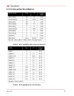
Table 24   ULI Compatible Wheelock Horns/Strobes

Wheelock

Type

Cd

Voltage 

(FWR)

NS-2415W-FR(W)

H/S

15

20-31

NS-241575W-FR(W)

H/S

15/75

20-31

NS-2430W-FR(W)

H/S

30

20-31

NS-2475W-FR(W)

H/S

75

20-31

NS-24110W-FR(W)

H/S

110

20-31

NS4-2415W-FR(W)

H/S

15

20-31

NS4-241575W-FR(W)

H/S

15/75

20-31

NS4-2430W-FR(W)

H/S

30

20-31

NS4-2475W-FR(W)

H/S

75

20-31

NS4-24110W-FR(W)

H/S

110

20-31

NS = 2-wire, NS4 = 4-wire

AS-2415W-FR(W)

S

15

20-31

AS-241575W-FR(W)

S

15/75

20-31

AS-2430W-FR(W)

S

30

20-31

AS-2475W-FR(W)

S

75

20-31

AS-24110W-FR(W)

S

110

20-31

AS4-2415C-FR(W)

S

15

20-31

AS4-2430C-FR(W)

S

30

20-31

AS4-2475C-FR(W)

S

75

20-31

AS4-24110C-FR(W)

S

110

20-31

AH-24-R

H

-

20-31

AH-24-WP-R

H

-

20-31

MT-24-R

H

20-31

MT4-24-R

H

20-31

MT-24-SL-VFR

H/S

15

20-31

MT-24-SLM-VFR

H/S

15/75

20-31

MT-24-MS-VFR

H/S

30

20-31

MT-24-IS-VFR

H/S

75

20-31

MT-24-WM-VFR

H/S

117

20-31

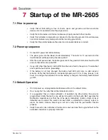
Содержание MR-2605

Страница 1: ...LT 2016 Rev 4 July 2010 Secutron MR 2605 Five Zone Fire Alarm Control Panel Installation Manual...

Страница 2: ......

Страница 3: ...e MR 2605 13 2 2 Optional Accessories 14 2 3 MR 2605 Overview 15 2 3 1 Zone Label Insert 16 2 4 Planning Your Installation 16 2 5 Electrical Specifications 17 2 6 Module Current Ratings 18 2 7 Standby...

Страница 4: ...only 38 6 MR 2605 System Programming 6 1 Entering Installer Programming Mode 40 6 1 1 Using the LED Indicators to Program the System 41 6 1 2 Using the Silence Trouble and Silence Alarm Controls to P...

Страница 5: ...Programming Section 3 57 8 6 Waterflow Programming Section 4 57 8 7 50 60Hz Option Section 5 58 9 Appendix ULI Compatible Smoke Detectors 9 1 ULI Compatible Smoke Detector Bases 61 9 2 ULI Compatible...

Страница 6: ...Secutron Inc vi...

Страница 7: ...necting 2 Wire Alarm Initiating Devices 27 Figure 10 Connecting 4 Wire Smoke Detectors 27 Figure 11 Connecting NAC Devices Class B 28 Figure 12 Connecting NAC Devices Class A 28 Figure 13 Connecting B...

Страница 8: ...Secutron Inc viii...

Страница 9: ...ce and NAC2 Strobe Mode Programming 45 Table 13 LED Indicators for Signal Silence Inhibit Timer and Audible Walk Test Programming 46 Table 14 LED Indicators for Waterflow Alarms Programming 47 Table 1...

Страница 10: ...Secutron Inc x...

Страница 11: ...Sprinkler Supervisory WF Waterflow 1 2 Codes Standards and Installation Requirements 1 2 1 Relevant codes and standards The MR 2605 fire alarm control panel is designed to meet the requirements of NFP...

Страница 12: ...ified for proper installation and operation when the initial installation is ready for inspection by the Local Authority Having Jurisdiction any system component is added changed or deleted any progra...

Страница 13: ...te c w display and control printed circuit board Zone label insert Battery compartment dead front plate Main control PCB Transformer Installation manual Hardware pack 2 NAC EOL resistors 4 7 K 5 W 5 Z...

Страница 14: ...trouble visual indicator AC on visual indicator and a trouble silence lamp test switch Mounts remotely to a single gang electrical box and is connected to the main panel via the 4 wire secur bus MR 2...

Страница 15: ...15 2 3 MR 2605 Overview Figure 1 MR 2605 cabinet with door closed Figure 2 MR 2605 display and controls Figure 3 MR 2605 Cabinet Overview CPU FAULT Note Use Security Screw provided to meet UL 864 Rev...

Страница 16: ...ted modules and devices Using the chart in this manual calculate the standby battery size that will meet the standby time required Include all components that will draw current from the standby batter...

Страница 17: ...aximum current sink Relays common alarm trouble Form C contact 2 Amp 30 VDC resistive power limited source NAC Outputs 24 volts full wave rectified DC 1 5 Amps max Power limited 3 0 Amps total for bot...

Страница 18: ...draw for each device connected to the NAC For each NAC calculate the total current in alarm and put that number mA in the Alarm column 5 For each added module in the system multiply the number of mod...

Страница 19: ...arm time required in hours 5 min 08 Hr 30 min 0 5 Hr 12 Multiply the alarm Amps times the alarm time to get the alarm Amp Hr required 13 Add the standby Amp Hr to the alarm Amp Hr for the total Amp Hr...

Страница 20: ...andby x Alarm 69 x 1 69 Zone 2 Standby x Alarm 69 x 1 Zone 3 Standby x Alarm 69 x 1 Zone 4 Standby x Alarm 69 x 1 Zone 5 Standby x Alarm 69 x 1 3 NAC 1 Alarm x NAC 2 Alarm x 4 MR 2605 T Standby 15 x A...

Страница 21: ...me required 0 08 or 0 5 Hr 11 Alarm Amp Hr multiply 7 10 Amps Hr Amp Hr 12 Total Amp Hr standby Amp Hr 9 alarm Amp Hr 11 Amp Hr 13 Multiply the total Amp Hr by the safety margin 1 20 14 Total battery...

Страница 22: ...anel 3 1 Environmental Specifications Consider the following conditions when selecting a mounting location for the MR 2605 panel Operating temperature 32 F to 122 F 0 C to 50 C Humidity 95 RH non cond...

Страница 23: ...e panel comes completely assembled from the factory Remove the lower dead front for access to the battery compartment Remove display control panel for access to AC connections Figure 5 Panel Assembly...

Страница 24: ...Secutron Inc 24 3 3 Mounting the MR 2605 Figure 6 Mounting Dimensions Figure 7 Knockout Locations Dimensions in inches...

Страница 25: ...upervised for opens shorts and ground fault Power limited AUX Auxiliary power output 24 VDC filtered and regulated 500 mA max 400 mV P P ripple power limited Aux power shorts must be restored by remov...

Страница 26: ...Alarm relay is normally de energized Contact is shown in the de energized state Contacts are rated 30 VDC 2 Amps max Z1 Zone 1 positive input Z1 Zone 1 negative input Zone output is 24 VDC nominal to...

Страница 27: ...m total loop wire resistance 100 ohms Program zone as Type 1 Smoke and contact devices instant alarm default Type 2 Smoke auto verify and contact as instant Figure 10 Connecting 4 Wire Smoke Detectors...

Страница 28: ...ting NAC Devices Class A and Class B Figure 11 Connecting NAC Devices Class B Figure 12 Connecting NAC Devices Class A Wire Gauge Distance feet Distance meters 18 7 690 2 345 Maximum loop resistance i...

Страница 29: ...25 615 188 978 297 1 538 469 2 500 762 5 00 0 50 308 94 488 149 769 235 1 250 381 2 70 0 75 205 63 325 99 513 156 833 254 2 00 1 00 154 47 244 74 385 117 625 191 1 60 1 25 123 38 195 59 308 94 500 15...

Страница 30: ...tional Devices See installation sheets for the remote devices for detailed wiring and address setup Maximum of 4 MR 2605 T per panel Maximum of 4 MR 2605 AT per panel 240V 50Hz 120V 60Hz GND N Primary...

Страница 31: ...2 540 774 4 000 1 220 75 505 154 1 280 390 2 030 619 3 200 976 90 421 128 1 065 325 1 690 515 2 670 814 105 361 110 915 279 1 450 442 2 285 697 120 315 96 800 244 1 270 387 2 000 610 135 281 86 710 2...

Страница 32: ...he Reset Programming Mode on page 48 for information on adding and deleting devices on the Secur bus Table 8 Secur bus Devices Note Shielded wire has a much higher capacitance value and distances are...

Страница 33: ...extend this timer While the signal silence inhibit timer is counting down if the Silence Alarm button is pressed the panel will sound a 1 second error tone on the common trouble buzzer The NACs remai...

Страница 34: ...sory After silencing a fire supervisory a subsequent fire supervisory from another zone will resound the trouble supervisory buzzer and the new zone supervisory LED flashes until the Silence Trouble b...

Страница 35: ...econd on off deactivates Signals Silenced LED turns on Ground on extended conductor turns on sounds second on off deactivates Ground LED turns on AC fails completely or is low for more than 10 seconds...

Страница 36: ...reset period the panel will activate the NACs as programmed If there are no alarms but one or more Supervisory zones is still off normal after the reset period the panel will sound the trouble buzzer...

Страница 37: ...any remote connection is not activated 3 To return the system to normal operation press the Walk Test button If you do not press the Walk Test button the system will return to normal operation after...

Страница 38: ...y NAC2 can be set in this mode 5 9 2 Class A operation selections If the panel NACs are set for class A operation then there is only one NAC In this configuration the NAC output can only be set for st...

Страница 39: ...ne Programming NAC Sounding Rate NAC Auto Silence and NAC2 Strobe Mode 60 Second Signal Silence Inhibit and Audible Walk Test Waterflow Programming Reference AC Line Frequency 50 or 60 Hz There are tw...

Страница 40: ...e the lower front cover and locate the Walk Test Switch behind the control panel PCB as shown in Figure 17 Locating the Walk Test Switch 2 Press and hold the Walk Test Switch for two seconds The commo...

Страница 41: ...rent programmable function Pressing the Silence Trouble button cycles to the next programmable function 6 1 3 Using the Reset System and Lamp Test Controls Pressing the Reset System control enters the...

Страница 42: ...ramming Function Descriptions 6 3 1 Zone Programming Zone Programming is the first Programmable function Each of the 5 zones can be configured as one of the following Instant Alarm Waterflow Zone Supe...

Страница 43: ...lt in delay of 30 seconds or more The overall maximum waterflow alarm initiation delay allowed is 90 seconds NFPA A 5 6 2 1996 edition Activating the contact on a Waterflow alarm initiating device ins...

Страница 44: ...to cycle through the Zones To proceed to the next programming function cycle through the 2 zones The Trouble LED flashes when the panel is in programming mode The NAC1 Panel Status LED will illuminate...

Страница 45: ...D Alarm Supervisory and Trouble LED s Programmable Setting Description Automatic Signal Silence disabled The panel will not silence the NACs automatically Automatic Signal Silence enabled Silences all...

Страница 46: ...ing the Silence Alarm button turns off the NACs at any time Setting NAC2 as a strobe disables removes the ability to silence NAC2 by pressing the Silence Alarm Button See 6 3 3 NAC Automatic Signal Si...

Страница 47: ...ow zones causes an immediate alarm in the panel Waterflow Delay Timer Enabled The panel starts a 60 second timer when the first Waterflow zone enters alarm The panel will not restart the timer on subs...

Страница 48: ...Reset Programming Mode The Reset Programming mode allows for the following Removing a Module Adding a Module Default the System Enter the Reset Programming Mode as described in the following steps Ho...

Страница 49: ...The trouble buzzer is silent and the zone 1 alarm LED turns on steady The common trouble LED continues to flash You can now cycle through the Installer Programming Mode 6 To exit immediately press an...

Страница 50: ...the Installer Programming Mode The trouble buzzer is silent and the zone 1 alarm LED turns on steady The common trouble LED continues to flash You can now cycle through the Installer Programming Mode...

Страница 51: ...the most recent to the oldest 6 See the event table below which indicates the LED patterns used to indicate various events 7 To advance to the next event press the Silence Trouble switch 8 Once all 2...

Страница 52: ...Restore Flashing NAC1 Trouble LED NAC 1 Trouble Steady NAC1 Trouble LED NAC 1 Trouble Restore Flashing NAC2 Trouble LED NAC 2 Trouble Steady NAC2 Trouble LED NAC 2 Trouble Restore Flashing Battery Tro...

Страница 53: ...ere is a fault in the system Troubleshoot and repair the fault before proceeding If the battery is not fully charged the battery fault LED will come on after about 2 minutes Verify that the battery is...

Страница 54: ...ices for future reference section 8 Verify panel operations and feature selections by initiating alarms and troubles as described above 7 5 Final Verification Verify system operation and fault detecti...

Страница 55: ...tings for each programming section e g to change the zone type or to turn an option on or off 4 Press Silence Trouble to move to the next programming section e g to move from zone 1 to zone 2 5 The pa...

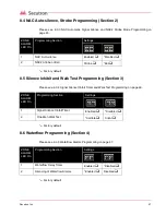
Страница 56: ...ogramming choices in the table below 8 3 NAC Temporal Steady Programming Section 1 Please see 6 3 2 NAC Sounding Rate Programming on page 44 Factory default ZONE ALARM LED On Zone No Type 00 05 Label...

Страница 57: ...Factory default 8 6 Waterflow Programming Section 4 Please see 6 3 5 Waterflow Alarms Programming on page 47 Factory default ZONE ALARM LED On Programming Section Settings 1 NAC Auto silence Enabled...

Страница 58: ...Secutron Inc 58 8 7 50 60Hz Option Section 5 Factory default ZONE ALARM LED On Programming Section Settings 2 AC power 50Hz or 60Hz 60Hz 50Hz...

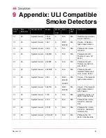
Страница 59: ...A N A N A Photoelectric with Thermal and Horn 2 wire 24VDC 01 25 System Sensor 2400AIT A N A N A Photoelectric with isolated Thermal and Horn 2 wire 24VDC 01 25 System Sensor 2451 A B401 B401B DH400 N...

Страница 60: ...ow Profile Ion 01 25 System Sensor 2151 2151A A B401 B401B DH400 N A Plug in Low Profile Photo 01 25 System Sensor 2100S A N A N A 2 wire direct wire Photoelectric 01 25 System Sensor 2100TS A N A N A...

Страница 61: ...10LP N A 2 wire flangeless 12 24VDC 25 System Sensor B116LP N A 2 wire base 24VDC form contact 25 System Sensor DH400 N A Duct Detector Mount 25 System Sensor RMK400 N A Recessed mount kit for Series...

Страница 62: ...41575 W A S 15 75 20 30 S2475 W A S 75 20 30 S24110 W A S 110 20 30 H24 W A H 20 30 MDL W A Synch Module 20 30 No suffix Red suffix W White suffix A Canadian version Gentex Type Cd Voltage FWR GEH24 H...

Страница 63: ...1 NS4 2475W FR W H S 75 20 31 NS4 24110W FR W H S 110 20 31 NS 2 wire NS4 4 wire AS 2415W FR W S 15 20 31 AS 241575W FR W S 15 75 20 31 AS 2430W FR W S 30 20 31 AS 2475W FR W S 75 20 31 AS 24110W FR W...

Страница 64: ...guarantee that interference will not occur in a particular installation If this equipment does cause harmful interference to radio or television reception which can be determined by turning the equip...

Страница 65: ...ation or after any changes to the system must be conducted by the Local Authority Having Jurisdiction Such inspections ensure installation has been carried out properly Power Failure Control units smo...

Страница 66: ...hose products Secutron does not warranty that the operation of the software will be uninterrupted or error free or that the software will meet any other standard of performance or that the functions o...

Страница 67: ...art of the system Security and Insurance Regardless of its capabilities an alarm system is not a substitute for property or life insurance An alarm system also is not a substitute for property owners...

Страница 68: ...t first obtain an authorization number Secutron Inc will not accept any shipment whatsoever for which prior authorization has not been obtained NOTE Unless specific pre authorization in writing is obt...

Страница 69: ...rm initiating devices and notification appliances must follow the manufacturer s guidelines as contained in their respective installation documents all applicable codes and the instructions of the Loc...

Страница 70: ...Secutron Inc 70...

Страница 71: ......

Страница 72: ...Niagara Falls New York 14305 Tel 888 SECUTRON 888 732 8876 Fax 905 660 4113 No part of this publication may be reproduced transmitted transcribed stored in a retrieval system or translated into any la...

Отзывы: