612
The thunder proof ground shall adopt the special ground cable from the monitor
control room to the ground object. The ground cable adopts copper insulation cable
or wire and its ground section shall be more than 20mm2.
The ground cable of the monitor system can not short circuit or mixed connected with
the strong alternative current cable.
For all the ground cables from the control room to the monitor system or ground cable
of other monitor devices, please use the copper resistance soft cable and its section
shall be more than 4mm2.
The monitor system usually can adopt the one-point ground.
Please connect the ground end of 3-pin socket in the monitor system to the ground
port of the system (protection ground cable)
4. The shortcut way to check the electric system using the digital multimeter
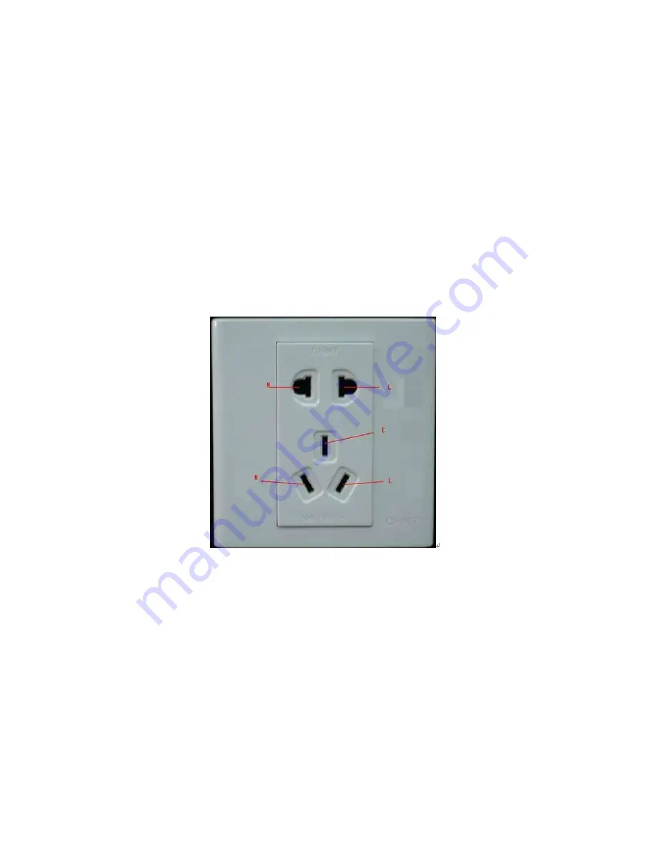
For 220V AC socket, from the top to the bottom, E (ground cable), N (neutral cable), L(live
cable). Please refer to the following figure.
There is a shortcut way to check these thee cables connection are standard or not (not the
accurate check).
Importance
In the following operations, the multimeter range shall be at 750V!
For E (earth cable)
Turn the digital multimeter to 750V AC, use your one hand to hold the metal end, and then
the other hand insert the pen to the E port of the socket. See the following figure. If the
multimeter shows 0, then you can see current earth cable connection is standard. If the
value is more than 10, then you can see there is inductive current and the earth cable
connection is not proper.
Содержание PENDVR-EL16M4K
Страница 1: ...PENDVR EL16M4K ELITE SERIES...
Страница 20: ...247 2 3 Connection Sample...
Страница 128: ...363 restore original status Figure 4 115 Figure 4 116 4 9 1 3 1Upgrade Camera...
Страница 151: ...386 Figure 4 137 Figure 4 138...
Страница 158: ...393 Figure 4 145 Step 2 Draw tripwire 1 Click Draw button to draw the tripwire See Figure 4 146 Figure 4 146...
Страница 162: ...397 Figure 4 149 Step 2 Draw the zone 1 Click draw button to draw the zone See Figure 4 150 Figure 4 150...
Страница 164: ...399 Figure 4 151 Step 2 Draw the zone 1 Click draw button to draw the zone See Figure 4 152 Figure 4 152...
Страница 166: ...401 Figure 4 153 Step 2 Draw the zone 1 Click Draw button to draw a zone See Figure 4 154...
Страница 172: ...407 Figure 4 157 Figure 4 158...
Страница 173: ...408 Figure 4 159 Figure 4 160...
Страница 174: ...409 Figure 4 161 Figure 4 162...
Страница 177: ...412 Figure 4 165 Figure 4 166...
Страница 178: ...413 Figure 4 167 Figure 4 168...
Страница 184: ...419 Figure 4 177 Figure 4 178 4 9 4 1 2 2 Trigger Snapshot...
Страница 186: ...421 Figure 4 180 Figure 4 181 4 9 4 1 2 3 Priority...
Страница 192: ...427 Figure 4 186 Figure 4 187...
Страница 197: ...432 Figure 4 193 Figure 4 194...
Страница 210: ...445 Figure 4 209 For digital channel the interface is shown as below See Figure 4 210 Figure 4 210...
Страница 217: ...452 Figure 4 218 Step 2 Click Add user button in Figure 4 218 The interface is shown as in Figure 4 219 Figure 4 219...
Страница 283: ...518 Figure 5 69 Figure 5 70...
Страница 299: ...534 device Figure 5 86 Figure 5 87...
Страница 305: ...540 Figure 5 94 Figure 5 95...
Страница 306: ...541 Figure 5 96 Figure 5 97 Please refer to the following sheet for detailed information...
Страница 310: ...545 Figure 5 101 Figure 5 102 Figure 5 103 Please refer to the following sheet for detailed information...
Страница 333: ...568 Figure 5 136 Note For admin you can change the email information See Figure 5 137...
Страница 363: ...598 448K 196M 512K 225M 640K 281M 768K 337M 896K 393M 1024K 450M 1280K 562M 1536K 675M 1792K 787M 2048K 900M...


