447
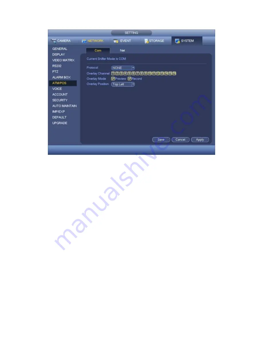
Figure 4-212
4.9.5.7.2 Network Type
The network type interface is shown as below. See Figure 4-213.
Please use network type if you using network to connect to the device. The interface is
generally the same as the COM mode. The protocol depends on your self-develop
protocol. The setup may vary since connected device or the protocol is not the same.
Here we take the ATM/POS protocol to continue.
Protocol: It is to set COM sniffer protocol. You need to select protocol according to
your own development situation.
Overlay mode: There are two options: preview and encode. Preview means overlay
the card number in the local monitor video. Encode means overlay the card number
in the record file. You can view the corresponding information when playback.
Overlay Position: Here you can select the proper overlay position from the dropdown
list.
Data group: There are total four groups IP.
Source IP: Source IP refers to host IP address that sends out information (usually it is
the device host.)
Destination IP: Destination IP refers to other systems that receive information.
Source port/destination port: Please input according to your own situation.
Record channel: It is for you to check record channel. The record channel applies to
one group (optional) only.
Frame ID: Six frame ID groups verification can guarantee information validity and
legal. You need to input start position, length, key and etc according to your
Содержание PENDVR-EL16M4K
Страница 1: ...PENDVR EL16M4K ELITE SERIES...
Страница 20: ...247 2 3 Connection Sample...
Страница 128: ...363 restore original status Figure 4 115 Figure 4 116 4 9 1 3 1Upgrade Camera...
Страница 151: ...386 Figure 4 137 Figure 4 138...
Страница 158: ...393 Figure 4 145 Step 2 Draw tripwire 1 Click Draw button to draw the tripwire See Figure 4 146 Figure 4 146...
Страница 162: ...397 Figure 4 149 Step 2 Draw the zone 1 Click draw button to draw the zone See Figure 4 150 Figure 4 150...
Страница 164: ...399 Figure 4 151 Step 2 Draw the zone 1 Click draw button to draw the zone See Figure 4 152 Figure 4 152...
Страница 166: ...401 Figure 4 153 Step 2 Draw the zone 1 Click Draw button to draw a zone See Figure 4 154...
Страница 172: ...407 Figure 4 157 Figure 4 158...
Страница 173: ...408 Figure 4 159 Figure 4 160...
Страница 174: ...409 Figure 4 161 Figure 4 162...
Страница 177: ...412 Figure 4 165 Figure 4 166...
Страница 178: ...413 Figure 4 167 Figure 4 168...
Страница 184: ...419 Figure 4 177 Figure 4 178 4 9 4 1 2 2 Trigger Snapshot...
Страница 186: ...421 Figure 4 180 Figure 4 181 4 9 4 1 2 3 Priority...
Страница 192: ...427 Figure 4 186 Figure 4 187...
Страница 197: ...432 Figure 4 193 Figure 4 194...
Страница 210: ...445 Figure 4 209 For digital channel the interface is shown as below See Figure 4 210 Figure 4 210...
Страница 217: ...452 Figure 4 218 Step 2 Click Add user button in Figure 4 218 The interface is shown as in Figure 4 219 Figure 4 219...
Страница 283: ...518 Figure 5 69 Figure 5 70...
Страница 299: ...534 device Figure 5 86 Figure 5 87...
Страница 305: ...540 Figure 5 94 Figure 5 95...
Страница 306: ...541 Figure 5 96 Figure 5 97 Please refer to the following sheet for detailed information...
Страница 310: ...545 Figure 5 101 Figure 5 102 Figure 5 103 Please refer to the following sheet for detailed information...
Страница 333: ...568 Figure 5 136 Note For admin you can change the email information See Figure 5 137...
Страница 363: ...598 448K 196M 512K 225M 640K 281M 768K 337M 896K 393M 1024K 450M 1280K 562M 1536K 675M 1792K 787M 2048K 900M...


