267
Model
HFD23/005-1ZS
HRB1-S-DC5V
times/MIN
)
times/MIN
)
Electrical
1×10
5
times
(
30
times/MIN
)
2.5×10
4
times
(
30
times/MIN
)
Working Temperature
-30
℃~
+70
℃
-40
℃~
+70
℃
3.8
RS485
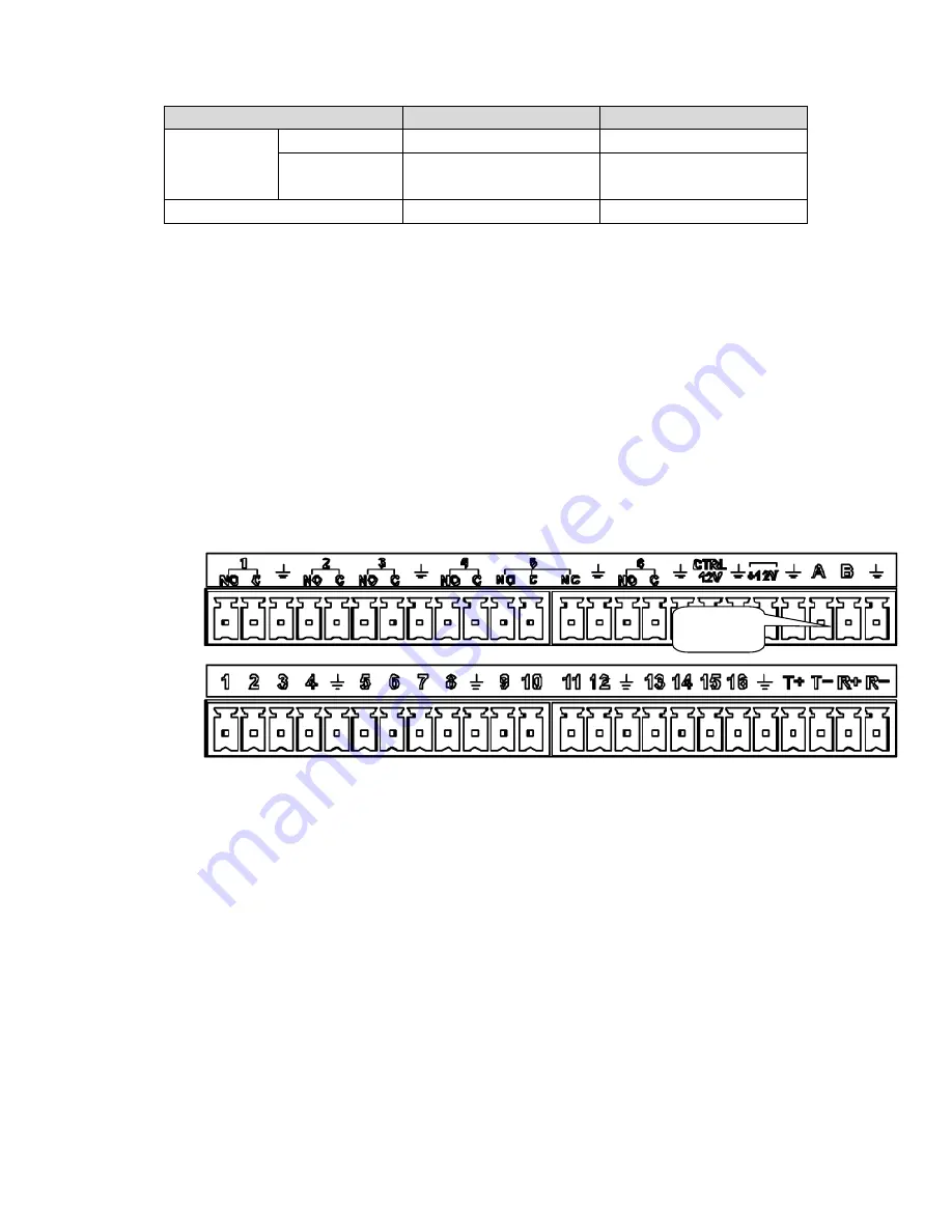
When the DVR receives a camera control command, it transmits that command up the coaxial
cable to the PTZ device. RS485 is a single-direction protocol; the PTZ
device can’t return any
data to the unit. To enable the operation, connect the PTZ device to the RS485 (A,B) input on
the DVR.
Since RS485 is disabled by default for each camera, you must enable the PTZ settings first.
This series DVRs support multiple protocols such as Pelco-D, Pelco-P.
To connect PTZ devices to the DVR:
1. Connect RS485 A,B on the DVR rear panel.
2. Connect the other end of the cable to the proper pins in the connector on the camera.
3. Please follow the instructions to configure a camera to enable each PTZ device on the
DVR.
Figure 3-3
3.9
Other Interfaces
There are still other interfaces on the DVR, such as USB port.
485 Port
Содержание PENDVR-EL16M4K
Страница 1: ...PENDVR EL16M4K ELITE SERIES...
Страница 20: ...247 2 3 Connection Sample...
Страница 128: ...363 restore original status Figure 4 115 Figure 4 116 4 9 1 3 1Upgrade Camera...
Страница 151: ...386 Figure 4 137 Figure 4 138...
Страница 158: ...393 Figure 4 145 Step 2 Draw tripwire 1 Click Draw button to draw the tripwire See Figure 4 146 Figure 4 146...
Страница 162: ...397 Figure 4 149 Step 2 Draw the zone 1 Click draw button to draw the zone See Figure 4 150 Figure 4 150...
Страница 164: ...399 Figure 4 151 Step 2 Draw the zone 1 Click draw button to draw the zone See Figure 4 152 Figure 4 152...
Страница 166: ...401 Figure 4 153 Step 2 Draw the zone 1 Click Draw button to draw a zone See Figure 4 154...
Страница 172: ...407 Figure 4 157 Figure 4 158...
Страница 173: ...408 Figure 4 159 Figure 4 160...
Страница 174: ...409 Figure 4 161 Figure 4 162...
Страница 177: ...412 Figure 4 165 Figure 4 166...
Страница 178: ...413 Figure 4 167 Figure 4 168...
Страница 184: ...419 Figure 4 177 Figure 4 178 4 9 4 1 2 2 Trigger Snapshot...
Страница 186: ...421 Figure 4 180 Figure 4 181 4 9 4 1 2 3 Priority...
Страница 192: ...427 Figure 4 186 Figure 4 187...
Страница 197: ...432 Figure 4 193 Figure 4 194...
Страница 210: ...445 Figure 4 209 For digital channel the interface is shown as below See Figure 4 210 Figure 4 210...
Страница 217: ...452 Figure 4 218 Step 2 Click Add user button in Figure 4 218 The interface is shown as in Figure 4 219 Figure 4 219...
Страница 283: ...518 Figure 5 69 Figure 5 70...
Страница 299: ...534 device Figure 5 86 Figure 5 87...
Страница 305: ...540 Figure 5 94 Figure 5 95...
Страница 306: ...541 Figure 5 96 Figure 5 97 Please refer to the following sheet for detailed information...
Страница 310: ...545 Figure 5 101 Figure 5 102 Figure 5 103 Please refer to the following sheet for detailed information...
Страница 333: ...568 Figure 5 136 Note For admin you can change the email information See Figure 5 137...
Страница 363: ...598 448K 196M 512K 225M 640K 281M 768K 337M 896K 393M 1024K 450M 1280K 562M 1536K 675M 1792K 787M 2048K 900M...


