background image


4-34


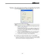
Deleting a group 

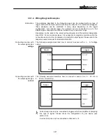
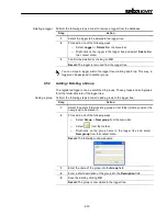
Perform the following steps in order to remove a group from the logger tree:  

Step 

Action 

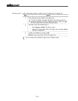
Select the group to be deleted in the logger tree. 

If a group is deleted, all loggers assigned to this group and its sub-
groups are deleted too and the collected data is lost. Move the logger 
to another group first, if you want to keep the data. 

Proceed in one of the following ways: 

o


Select Group -> Delete from the menu bar. 

o


Right-click on the group name in the logger tree and select Delete 
from the context menu. 

Confirm the deletion by clicking on OK

Result: The group is removed from the logger tree. 


You can move a group within the logger tree via drag and drop. 

Содержание Sebalog D

Страница 1: ...d Locating Technologies Leitungsortung Line Locating Rohrleitungsnetze Water Networks Kommunikationsnetze Communication Networks Elektrizit tsnetze Power Networks Issue 1 09 2008 5 V Alarm IN Operatin...

Страница 2: ......
Страница 3: ...nic Mess und Ortungstechnik GmbH Hagenuk KMT Kabelmesstechnik GmbH Dr Herbert Iann Str 6 D 96148 Baunach Phone 49 9544 68 0 Fax 49 9544 22 73 R deraue 41 D 01471 Radeburg Dresden Phone 49 35208 84 0 F...

Страница 4: ...m the date of delivery Each component supplied by SebaKMT within the context of warranty will also be covered by this warranty for the remaining period of time but for 90 days at least Each measure to...

Страница 5: ...1 4 Wiring Diagram Examples 3 21 3 3 2 Connecting a Tube to an Internal Pressure Sensor 3 25 3 4 Commissioning the Logger 3 26 3 4 1 Positioning the Logger 3 26 3 5 Positioning the GSM Antenna 3 26 3...

Страница 6: ...ions 5 47 5 4 6 Summary Messages 5 47 5 4 7 Testing the GSM Settings 5 48 5 4 7 1 Testing SMS Email Transmission 5 48 5 4 7 2 Testing FTP Data Transfer 5 50 5 4 8 Finishing the Communication Setup 5 5...

Страница 7: ...ries is subject to regulations based on the UN Model Regulations Transport of Dangerous Goods ST SG AC 10 1 Please inform yourself about the transportation requirements and follow them when shipping t...

Страница 8: ...e Sebalog D is specified by the following parameters Parameter Value Communication USB interface Wireless 868 915 MHz GSM GPRS modem 850 900 1800 1900 MHz Inputs outputs 1 2 or 4 freely programmable c...

Страница 9: ...number PN on the bottom of the logger you can identify the type of your device Single channel versions Item number Type Item number Type 820013543 LOG D1 B 820013549 LOG D1 GSM P1 16 820013544 LOG D1...

Страница 10: ...013493 LOG D4 I GSM P2 40 Type number The type number consists of the following segments Due to the large amount of possible configurations this manual cannot state explicitly whether or not a describ...

Страница 11: ...sts of the following operating controls and indicators Item Description On off contact area I O control lamp not lit Logger is switched off green flashing Logger is switched on and in energy saving mo...

Страница 12: ...the USB socket is always part of the assembly it depends on the configuration of the logger whether the other connectors are existent The Sebalog D offers the following connectors Item Description IN...

Страница 13: ...a PC must be connected to the USB DC ext socket 820012451 E Box USB Allows wireless data transfer between the logger and a PC within a range of about 100 m 820009270 USB cable 1 m For connecting the E...

Страница 14: ...3 2 Preparing the Logger for GSM Connectivity If the data collected by the logger should be periodically transferred to a FTP server or if an alarm notification via email SMS is required the followin...

Страница 15: ...observed If the logger is older then six months and if the front panel has not been changed during the last six months a new front panel including a new rubber seal must be installed A new front panel...

Страница 16: ...Basics Introduction One end of the VK 75 VK 76 connection cables used for connecting equipment to the logger is uncoated and ten colour coded wires stick out of it According to its colour each of the...

Страница 17: ...essure sensors the respective channels are in use and must not be connected to external sensors Corresponding to these conventions the following channel allocations apply Channel 1 Channel 2 Channel 3...

Страница 18: ...e connected to green Switching input 2 An alarm triggering device with a voltage output of 0 5 V can be connected between this wire and the purple wire GND yellow Switching output relay 2 OUT pink Swi...

Страница 19: ...ected to the USB DC ext socket via the VK 76 connection cable VK 75 pin assignment In combination with a multi channel logger the VK 75 connection cable has the following pin assignment Wire Descripti...

Страница 20: ...y 1 OUT yellow Switching output relay 2 OUT pink Switching outputs IN An electric circuit with an external DC power supply up to 12 V 1 A can be connected to each switching output If an internal relay...

Страница 21: ...a resistance into the connection setup in order to dampen or amplify the output signal Please refer to the respective sensor manual for detailed information Connecting a sensor with the output signal...

Страница 22: ...a sensor with a 0 Hz 1000 Hz frequency output Example 1 the logger does not supply the operating voltage for the sensor Example 2 the logger supplies the operating voltage for the sensor Sensor Logger...

Страница 23: ...nsors transmit a pulse to the logger whenever the value of the measurement crosses a certain threshold Example 1 the logger does not supply the operating voltage for the sensor Example 2 the logger su...

Страница 24: ...ation one or two of the internal relays are switched in order to activate trigger the load connected to the respective switching output in this case a signal lamp and a SMS and or email can be sent to...

Страница 25: ...erpressure Do not exceed the measuring range in order to avoid irreparable damage to the sensor Make sure no dirt or rust can ingress inside the sensors In case of doubt use a filter There must not be...

Страница 26: ...ensure error free data transfer Care shall be taken to ensure that cables and their connections are not subjected to tensile load Do not hang the logger on its connection cables Do not bend the connec...

Страница 27: ...er has been switched on it automatically starts logging as specified in its configuration The device keeps logging even if a data transfer takes place or an alarm is triggered In order to switch the l...

Страница 28: ...e Software To install the SebaDataView software insert the provided CD into your CD ROM drive execute the SDV setup exe and follow the instruction on the screen The application is installed to the C P...

Страница 29: ...on the environmental conditions via radio link That way you are able to initiate a data transfer without sitting next to the device If a logger receives a signal from the E Box addressed to it it cha...

Страница 30: ...driver is not causing any danger for your system you can continue the installation 4 3 2 Connecting the Logger via Direct Connection Connecting the logger To establish a direct connection to a PC use...

Страница 31: ...the user interface Make your choice and click on OK The user interface of the software consists of the following basic elements Menu bar Offers access to all functions of the software Toolbar Offers q...

Страница 32: ...n one of the following ways o Select Group New logger from the menu bar o Select from the toolbar o Right click on the group name in the logger tree and select New logger from the context menu 2 Resul...

Страница 33: ...p The registered loggers can be combined in groups These groups and sub groups form the folder structure of the logger tree Adding a group Perform the following steps in order to add a group to the lo...

Страница 34: ...are deleted too and the collected data is lost Move the logger to another group first if you want to keep the data 2 Proceed in one of the following ways o Select Group Delete from the menu bar o Rig...

Страница 35: ...is connected to the PC and switched on 2 Select the logger you want to configure in the logger tree Proceed in one of the following ways o Select Logger Configuration from the menu bar o Select from...

Страница 36: ...5 76 connection cables For a detailed description please refer to section 3 3 1 Please pay regard to the fixed channel allocations when configuring internal pressure sensors or sensors with current ou...

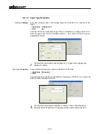
Страница 37: ...d to each other If a predefined sensor from the drop down list has been selected these parameters have been automatically populated However in the case of a customer specific sensor the input type car...

Страница 38: ...result the fields must be populated as follows The maximum permissable input voltage is 5 V Higher input voltages may damage the device Input type Frequency A level meter with frequency output is inst...

Страница 39: ...nother channel A flowmeter is connected to channel 2 In addition to the flow rate itself the flow direction shall be determined For this purpose a sensor which indicates the flow direction by means of...

Страница 40: ...ividually specified for each channel Configuring alarms Perform the following steps to configure the alarm thresholds and the alarm destinations Steps Action 1 Activate the Alarm active checkbox in or...

Страница 41: ...lower threshold the other way around A relay cannot be assigned to more than one alarm If a relay is already included in an existing channel configuration it cannot be used in combination with any ot...

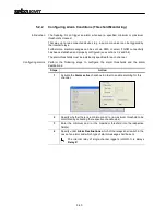
Страница 42: ...s shown in section 3 3 1 4 As known from the channel configuration an alarm can trigger up to two internal relays Furthermore alarm messages can be sent via SMS or email if GSM connectivity has been e...

Страница 43: ...V is interpreted as 0 V while voltages higher than 2 5 V are interpreted as 5 V In order to ensure a reliable classification the actual voltage values should not be too close to 2 5 V 2 Specify under...

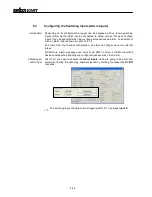
Страница 44: ...is going to be established during a specific timeframe only e g during daytime the range of this timeframe has to be specified via the Radio on from and Radio is off from fields Out of this timeframe...

Страница 45: ...ontract Further information can be obtained from the website or the hotline of the mobile network operator If necessary request guidance for setting up data communication in particular SebaKMT cannot...

Страница 46: ...r email transmission into the respective fields If the mail server of your company is not capable for this task e g due to a firewall a webmail account from an internet service provider e g Yahoo or G...

Страница 47: ...plus two leading zeros must be created inside this folder Example In order to enable FTP data transfer for a logger with the ID 000815 the logd 00000815 folder must be crated on the FTP server 5 4 5...

Страница 48: ...1 Testing SMS Email Transmission Perform the following steps to send a test SMS email Step Action Click on the Test GSM settings button 1 Result A new window appears Click on the Send Test SMS button...

Страница 49: ...M card configuration see section 5 4 1 In the case of bad signal quality SignalQ 0 or 1 it may help to move the GSM antenna in a better position see section 3 5 If the network registration has failed...

Страница 50: ...reated the logger probably failed to establish a GSM connection or was not able to establish a connection to the server Click on the Read GSM log button in order to identify possible sources of the pr...

Страница 51: ...he last data or configuration readout Amongst others the remaining memory in percent and the supply voltage are indicated If EXT is displayed instead of an actual voltage value the logger is connected...

Страница 52: ...menu 3 Result A new window appears 4 If you would like to receive only these data sets which are not already contained in the local database check the Read only new data checkbox Otherwise all data s...

Страница 53: ...ys o Select from the toolbar o Right click on the logger in the logger tree and select Read data from the context menu 3 Result A new window appears 4 If you would like to receive only these data sets...

Страница 54: ...ram The curves of the different channels share in one diagram The X axis represents the timeline while the Y axis represents the measured values By clicking on a curve the channel is selected and the...

Страница 55: ...n the diagram hold down the mouse button and move the mouse in any direction in order to move the curves within the diagram Choose By selecting this item you can leave the Move or Magnify modes descri...

Страница 56: ...ggers which could be found 7 2 Real Time Measurement Proceed as follows to retrieve and display values of all channels in real time Step Action 1 Make sure the logger is connected to your PC either vi...

Страница 57: ...me pairs line by line is saved to the hard disk Proceed as follows Step Action 1 Mark the logger whose data you want to export in the logger tree Proceed in one of the following ways o Select Logger E...

Страница 58: ...ogger Step Action 1 Make sure the logger is connected to your PC either via USB cable or via E Box and that the logger is switched on 2 Select Program Settings Firmware Update from the menu bar 3 Ente...

Страница 59: ...ries Step Action 1 In order to replace the lithium batteries of the Sebalog D a special battery replacement set which contains all required cables and plugs and a new front panel has to be ordered fro...

Отзывы: