Section 09
PROPULSION AND DRIVE SYSTEMS
Sub-Section 01
(PROPULSION AND DRIVE SYSTEMS)
09-01-3
GENERAL
Some pump components can be changed to im-
prove boat performance in high altitude regions
between 1500
-
3000 m (5000
-
10 000 ft). Refer
to the service department for the latest specifica-
tions.
CAUTION : Such modifications should
only be performed by experience me-
chanics since they can greatly affect vehicle
performance.
JET PUMP INSPECTION ON JET
BOAT
To work on boat, securely install it on a stand.
Thus, if access is needed to water inlet area, it will
be easy to slide underneath boat.
A lift kit (P / N 295 000 120) can be used to install
boat on a stand.
Impeller Condition and Impeller
/
Wear
Ring Clearance
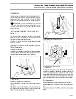
Impeller Condition
Condition of impeller, boot and ring can be quickly
checked from underneath of the jet boat. Remove
grill and look through water inlet opening.
1. Boot with ring
Impeller
/
Wear Ring Clearance
This clearance is critical for jet pump perfor-
mance.
Clearance can be checked from water inlet open-
ing, after inlet grill removal, or from venturi side,
after venturi
/
nozzle assembly removal.
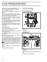
MEASURING FROM WATER INLET SIDE
1. Feeler gauge
MEASURING FROM VENTURI SIDE
1. Feeler gauge
Using a long feeler gauge 30 cm (12 in) blades,
measure clearance between impeller blade tip
and wear ring. Measure each blade at its center.
Clearance should not exceed 1.02 mm (.040 in). If
clearance is greater, disassemble jet pump and in-
spect impeller and wear ring. Renew worn parts.
Oil Inspection
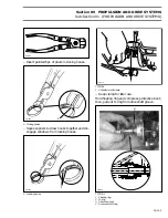
Detach adjuster of steering cable from nozzle.
Detach ball joint of VTS from trim ring (
Challeng-
er
).
Detach ball joint of shifter cable from reverse
gate.
-
F01J0DA
1
F01J0EA
1
F01J0FA
1
Содержание Challenger 5896
Страница 1: ......
Страница 2: ......
Страница 3: ...219 100 044 0 0 0 1996 Shop Manual 0 R ...
Страница 143: ...Section 08 ELECTRICAL Sub Section 01 OVERVIEW 08 01 3 1 Battery 2 Fuse block 3 Accessories F04H0YA 3 1 2 ...
Страница 152: ...Section 08 ELECTRICAL Sub Section 03 IGNITION SYSTEM 08 03 2 ELECTRICAL BOX Sportster F04H11S ...
Страница 154: ...Section 08 ELECTRICAL Sub Section 03 IGNITION SYSTEM 08 03 4 ELECTRICAL BOX Speedster F04H26S ...
Страница 251: ...Section 11 HULL DECK Sub Section 01 COMPONENTS 11 01 5 F04L3IS Loctite 242 ...
Страница 274: ......


