


Section 08
ELECTRICAL
Sub-Section 03
(IGNITION SYSTEM)
08-03-10
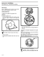
1. Tool slot
2. Flywheel mark
This mark becomes the reference when using
stroboscopic timing light.
CAUTION : Timing mark position verifica-
tion cannot be used as a timing proce-
dure, therefore, always check the timing with a
stroboscopic timing light at 6000 RPM after the
marks have been checked.
Checking Ignition Timing
NOTE :
To perform this procedure it is rec-
ommended to use a stroboscopic timing
light rated to work up to 6000 RPM.
To check ignition timing, use a timing light (P / N
295 000 078).
NOTE :
This timing light is battery powered
(2 batteries, type C) and therefore needs no
auxiliary power source.
The ignition components are affected by temper-
ature variation, therefore, timing must be checked
when engine is cold, after MAXIMUM 20 seconds
idling
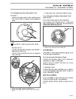
1. Connect timing light pick-up to MAG side spark
plug lead.
TYPICAL
1. Timing light pick-up on MAG side
2. Connect an induction-type tachometer to spark
plug wire.
3. Start engine and point timing light straight in
line with timing tool slot. Bring engine to 6000
RPM for a brief instant.
IMPORTAN :
Place shifter in forward or reverse
position to allow engine reaching 6000 RPM.
NOTE :
On this NIPPONDENSO system,
timing advance decreases as engine speed
increases. When marks are aligned at 6000 RPM,
spark occurrence is still Before Top Dead Center.
4. Check if PTO flywheel mark (or reference one
previously scribed) aligns with timing tool slot.
CAUTION : If engine is to be run more
than a few minutes, connect coupler hose
(P / N 295 500 099) to properly cool engine.
If timing marks align, timing is correct.
CAUTION : Always verify timing marks
with TDC gauge before checking the tim-
ing. Particularly if PTO flywheel has been re-
placed, it could possibly move slightly.
F01H31A
2
1
-
'
'
6000
1
F01H2IA
'
-
-
Содержание Challenger 5896
Страница 1: ......
Страница 2: ......
Страница 3: ...219 100 044 0 0 0 1996 Shop Manual 0 R ...
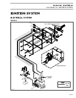
Страница 143: ...Section 08 ELECTRICAL Sub Section 01 OVERVIEW 08 01 3 1 Battery 2 Fuse block 3 Accessories F04H0YA 3 1 2 ...
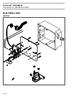
Страница 152: ...Section 08 ELECTRICAL Sub Section 03 IGNITION SYSTEM 08 03 2 ELECTRICAL BOX Sportster F04H11S ...
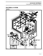
Страница 154: ...Section 08 ELECTRICAL Sub Section 03 IGNITION SYSTEM 08 03 4 ELECTRICAL BOX Speedster F04H26S ...
Страница 251: ...Section 11 HULL DECK Sub Section 01 COMPONENTS 11 01 5 F04L3IS Loctite 242 ...
Страница 274: ......


