


Section 08
ELECTRICAL
Sub-Section 09
(INSTRUMENTS AND ACCESSORIES)
08-09-3
FUEL / OIL GAUGE
The fuel / oil gauge has a pointer which indicates
fuel level. To verify if fuel pointer works, first
touch start /stop button (with safety lanyard re-
moved) to activate electrical system for about 33
seconds.
The oil level pilot lamp is part of the fuel gauge. It
will light when injection oil level is low.
1. Low oil warning light
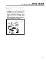
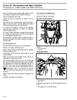
Fuel Baffle Pick-Up Sensor Verification
The baffle pick-up has an integrated fuel sensor.
To verify fuel sensor, a resistance test should be
performed with an ohmmeter allowing the float to
move up through a sequence.
1. Pick-up tube
2. Fuel sensor
3. Baffle pick-up
The resistance measured between BLACK /
GREEN and GREEN wires must be in accordance
with fuel level (measured from under the flange)
as specified in the following charts.
Speedster
Challenger
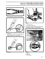
Low-Level Oil Sensor
The sensor sends the signal to the low-oil level
light in the fuel gauge.
The bottom of the sensor has a small reservoir
with 2 small holes underneath to let the oil enter
inside and 1 at the top to let the air enter to allow
the oil flowing out.
1
0
Bombardier
F01G07A
1
F01F20A
1
2
3
FUEL LEVEL AND RESISTANCE
FUEL LEVEL
RESISTANCE
mm
(in)
(
Ω
)
From 46.6
@
68.6
(1-27/32 à 2-45/64)
0
±
0.1
From 68.6
@
92.3
(2-45/64 à 3-41/64)
17.8
±
0.2
From 92.3
@
116.0
(3-41/64 à 4-37/64)
27.8
±
0.3
From 116.0
@
139.7
(4-37/64 à 5-1/2)
37.8
±
0.4
From 139.7
@
163.4
(5-1/2 à 6-7/16)
47.8
±
0.54
From 163.4
@
187.1
(6-7/16 à 7-3/8)
57.8
±
0.6
From 187.1
@
210.8
(7-3/8 à 8-19/64)
67.8
±
0.7
From 210.8
@
234.5
(8-19/64 à 9-15/64)
77.8
±
0.8
From 234.5 and more
(9-15/64) and more
89.8
±
0.9
FUEL LEVEL AND RESISTANCE
FUEL LEVEL
RESISTANCE
mm
(in)
(
Ω
)
full
299 and more
11.8 and more
0
±
2.2
7/8
272 @ 298
10.7 @ 11.7
17.8
±
2.2
3/4
247 @ 271
9.7 @ 10.6
27.8
±
2.2
5/8
220 @ 246
8.7 @ 9.6
37.8
±
2.2
1/2
194 @ 219
7.6 @ 8.6
47.8
±
2.2
3/8
162 @ 193
6.4 @ 7.5
57.8
±
2.2
1/4
130 @ 161
5.1 @ 6.3
67.8
±
2.2
1/8
86 @ 129
3.4 @ 5.0
77.8
±
2.2
empty
0 @ 85
0 @ 3.3
89.8
±
2.2
Содержание Challenger 5896
Страница 1: ......
Страница 2: ......
Страница 3: ...219 100 044 0 0 0 1996 Shop Manual 0 R ...
Страница 143: ...Section 08 ELECTRICAL Sub Section 01 OVERVIEW 08 01 3 1 Battery 2 Fuse block 3 Accessories F04H0YA 3 1 2 ...
Страница 152: ...Section 08 ELECTRICAL Sub Section 03 IGNITION SYSTEM 08 03 2 ELECTRICAL BOX Sportster F04H11S ...
Страница 154: ...Section 08 ELECTRICAL Sub Section 03 IGNITION SYSTEM 08 03 4 ELECTRICAL BOX Speedster F04H26S ...
Страница 251: ...Section 11 HULL DECK Sub Section 01 COMPONENTS 11 01 5 F04L3IS Loctite 242 ...
Страница 274: ......