3.25
Date Code 20050919
Instruction Manual
SEL-387-0, -5, -6 Relay
Differential, Restricted Earth Fault, Thermal, and Overcurrent Elements
Temperature Measurement (SEL-387-5 and SEL-387-6 Relays)
Step 5. Ensure that there will be no wye windings with wye CTs and a
setting of WnCTC = 0.
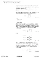
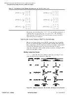
In this case the primary winding is wye-connected and has wye-
connected CTs. In
we set W1CTC at zero because
Winding 1 was the reference winding. However, this setting
violates the condition that WnCTC not equal 0. Instead of a
zero shift, we must shift Winding 1 360 degrees by setting
W1CTC = 12. This solves the zero-sequence current problem.
The process is now complete. The relay receives the three
settings as W1CTC = 12, W2CTC = 7, and W3CTC = 5.
Winding Line-to-Line Voltages
Enter the nominal line-to-line transformer terminal voltages. If a load tap
changer is included in the transformer differential zone, assume that it is in the
neutral position. The setting units are kilovolts.
Current TAP
The relay uses a standard equation to set TAP
n
, based on settings entered for
the particular winding. (
n
denotes the winding number.)
Equation 3.12
The relay calculates TAP
n
with the following limitations:
➤
The tap settings are within the range 0.1 • I
N
and 31 • I
N
➤
The ratio TAP
MAX/
TAP
MIN
≤
7.5
Restrained Element Operating Current Pickup
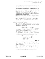
The O87P setting range is 0.1 to 1.0; we suggest an O87P setting of 0.3. The
setting must be at a minimum for increased sensitivity but high enough to
avoid operation because of steady-state CT error and transformer excitation
current. The setting must also yield an operating current greater than or equal
to 0.1 • I
N
, when multiplied by the smallest of TAP1 through TAP4. Stated
another way,
Equation 3.13
Restraint Slope Percentage
Example:
The current transformer error, e, is equal to ±10 percent. In per unit:
e = 0.1
where:
C = 1 if W
n
CT setting = Y (wye-connected CTs)
C =
√
3 if W
n
CT setting = D (delta-connected CTs)
MVA = maximum power transformer capacity setting
(must be the same for all TAP
n
calculations)
VWDG
n
= winding line-to-line voltage setting, in kV
CTR
n
= current transformer ratio setting
TAPn
MVA
1000
•
3
VWDGn
CTRn
• •
-----------------------------------------------------------
C
•
=
O87P
MIN
0.1
I
N
•
(
)
TAP
MIN
------------------------
≥
Содержание SEL-387-0
Страница 10: ...This page intentionally left blank ...
Страница 16: ...This page intentionally left blank ...
Страница 56: ...This page intentionally left blank ...
Страница 350: ...This page intentionally left blank ...
Страница 388: ...This page intentionally left blank ...
Страница 456: ...This page intentionally left blank ...
Страница 494: ...This page intentionally left blank ...
Страница 528: ...This page intentionally left blank ...
Страница 536: ...This page intentionally left blank ...


