


2.18
SEL-387-0, -5, -6 Relay
Instruction Manual
Date Code 20050919
Installation
Circuit Board Configuration
Low-Level Analog Interface
SEL designed the SEL-387 main board to accept low-level analog signals as
an optional testing method.
Section 10: Testing and Troubleshooting
contains
a more detailed discussion of the patented Low-Level Test Interface; and
shows the pin configuration. The SEL RTS (Relay Test System)
interfaces with the relay through a ribbon cable connection on the main board.
With the front panel removed, the low-level interface connector is on the front
edge at the far right of the top board. Refer to
. Remove the ribbon
cable from the main board (top board), and connect the SEL RTS ribbon cable
to the main board. This removes the connection from the transformers in the
bottom of the relay chassis and connects the SEL RTS system for low-level
testing. Refer to the SEL
RTS Instruction Manual
for system operation. For
normal operation, be sure to properly reinstall the ribbon cable that connects
the transformers in the bottom of the chassis to the main board.
Clock Battery
for clock battery B1 location. This lithium battery powers
the relay clock (date and time) if the external power source is lost or removed.
The battery is a 3 V lithium coin cell. At room temperature (25°C) the battery
will operate nominally for 10 years at rated load.
Because little self-discharge of the battery occurs when an external source
powers the relay, battery life can extend well beyond the nominal 10 years.
The battery cannot be recharged.
If the relay does not maintain the date and time after power loss, replace the
battery. Follow the instructions previously described in
to remove the relay main board.
Remove the battery from beneath the clip and install a new one. The positive
side (+) of the battery faces up. Reassemble the relay as described in
Accessing the Relay Circuit Boards
. Set the relay date and time via serial
communications port or front panel (see
Section 8: Front-Panel Interface
).
Additional Interface
Board
We offer versions of the SEL-387 in a taller case size (3U) to accommodate
one additional circuit board. The additional board mounts below the main
board and above the analog input (transformer) board.
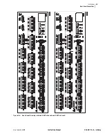
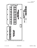
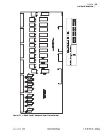
Three interface board types are available. Interface Board 2 has 12 standard
output contacts and 8 optoisolated inputs. Interface Board 4 has 4 standard
output contacts and 16 optoisolated inputs. Interface Board 6 has 12 hybrid
high current interrupting output contacts and 8 optoisolated inputs. These
latter contacts can interrupt as much as 10 A of dc current, as indicated in
Jumpers
As on the main board, the output contacts of Interface Boards 2 and 6 have
solder jumpers for configuring the output as either a form-A (normally open)
or form-B (normally closed) contact. When removing the board to change
jumpers, follow the procedure outlined in
Accessing the Relay Circuit Boards
Take precautions related to protection of components from damage due to
electrostatic discharge (ESD).
There is danger of explosion if the
battery is incorrectly replaced.
Replace only with Ray-O-Vac
®
no.
BR2335 or equivalent recommended
by manufacturer. Dispose of used
batteries according to the
manufacturer’s instructions.
!
CAUTION
NOTE:
The level-sensitive
optoisolated inputs on both interface
boards have no jumpers. You must
specify control voltage at the time of
order.
Содержание SEL-387-0
Страница 10: ...This page intentionally left blank ...
Страница 16: ...This page intentionally left blank ...
Страница 56: ...This page intentionally left blank ...
Страница 350: ...This page intentionally left blank ...
Страница 388: ...This page intentionally left blank ...
Страница 456: ...This page intentionally left blank ...
Страница 494: ...This page intentionally left blank ...
Страница 528: ...This page intentionally left blank ...
Страница 536: ...This page intentionally left blank ...


