


Operation
©
by Antriebs- & Regeltechnik Schimpf GmbH
60
Two calibration values can be adjusted in current or voltage mode for the calibration
characteristic curve of the analogue input. In current mode, the calibration values for 4
mA and 20 mA can be adjusted. In voltage mode, the calibration values for 2 V and 10
V can be adjusted.
In the
Mode 3
setting, the calibration values are adjusted for 4 mA or 2 V.
Important:
The corresponding setting must also be made on the “Analogue” DIP
switch.
Parameter 0:
4 mA is applied to the analogue input from a current source. Press and
hold the “Prog” button to store the new calibration values for 4 mA in the memory. The
“Prog” LED will flash briefly. If the new value is outside the valid range, the new value
cannot be stored in the memory (the “Prog” LED will not flash).
Parameter 1:
2 V is applied to the analogue input from a voltage source. Press and
hold the “Prog” button to store the new calibration values for 2 V in the memory. The
“Prog” LED will flash briefly. If the new value is outside the valid range, the new value
cannot be stored in the memory (the “Prog” LED will not flash).
Parameters 2-9:
Not assigned; when selected, the current setting is not changed
Mode 4: Calibrate analogue input 20 mA or 10 V value
The analogue input of the drive is calibrated at the factory.
Recalibrating the
analogue input is usually only necessary if there are very high requirements for angular
accuracy or, for example, if the connection cables are long.
Two calibration values can be adjusted in current or voltage mode for the calibration
characteristic curve of the analogue input. In current mode, the calibration values for 4
mA and 20 mA can be adjusted. In voltage mode, the calibration values for 2 V and 10
V can be adjusted.
Содержание 00-10/30 STEP
Страница 28: ...Connections by Antriebs Regeltechnik Schimpf GmbH 28 Figure 10 CPU board 00 15 Figure 11 Add on board 00 15 ...
Страница 69: ...Declaration of Conformity by Antriebs Regeltechnik Schimpf GmbH 69 Declaration of Conformity ...
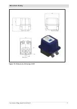
Страница 71: ...Dimensional drawing by Antriebs Regeltechnik Schimpf GmbH 71 Figure 15 Dimensions of drive type 00 15 ...
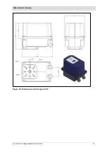
Страница 72: ...Dimensional drawing by Antriebs Regeltechnik Schimpf GmbH 72 Figure 16 Dimensions of drive type 01 15 ...