Connections
©
by Antriebs- & Regeltechnik Schimpf GmbH
30
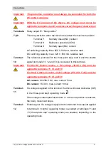
Description of the connections 00-10, 00-15 and 01-15
Important:
Control and regulation lines must be shielded.
Terminal:
1
The analogue signal (current/voltage) of the position feedback is output
at terminal 1 of the base board. The reference of the analogue signal is
connected to terminal 2.
Current source: max. 12V output voltage, max. load 500
Voltage source: max. 12V output voltage, max. 30 mA current
Terminal:
2
The reference potential GND for input and output signal lines (terminals
1 and 3) is connected to this terminal.
The ground is not galvanically isolated from the DC supply voltage.
There is a separation from PE.
Terminal:
3
The external setpoint input (current/voltage) is connected to terminal 3
of the base board. The reference of the analogue signal is connected to
terminal 2.
Max. input voltage: 12 V, current input: Load: 500
Terminal:
4
DC device version (18..30 V DC):
The positive conductor of the DC supply voltage is connected to this
terminal.
It is used to supply the drive with a continuous voltage.
AC device version (90..260 V AC):
The phase of the mains voltage is connected to this terminal.
It is used to supply the drive with a continuous voltage.
Terminal:
5
DC device version (18..30 V DC):
The ground of the supply voltage is connected to this terminal.
AC device version (90..260 V AC):
The neutral conductor of the mains voltage is connected to this terminal.
Terminal:
6
The protective conductor is connected to this terminal.
Содержание 00-10/30 STEP
Страница 28: ...Connections by Antriebs Regeltechnik Schimpf GmbH 28 Figure 10 CPU board 00 15 Figure 11 Add on board 00 15 ...
Страница 69: ...Declaration of Conformity by Antriebs Regeltechnik Schimpf GmbH 69 Declaration of Conformity ...
Страница 71: ...Dimensional drawing by Antriebs Regeltechnik Schimpf GmbH 71 Figure 15 Dimensions of drive type 00 15 ...
Страница 72: ...Dimensional drawing by Antriebs Regeltechnik Schimpf GmbH 72 Figure 16 Dimensions of drive type 01 15 ...


