Application Notes
P746/EN AP/G31
MiCOM P746
(AP) 6-
35
Treating this as an open bus coupler circuit breaker as before the topology algorithm will
have extended zone 1 with the area located between the CT and the circuit breaker. This
then fully replicates the scheme up to the open bus coupler CB. Remember that in this
example zone 2’s limit extended up to the circuit breaker but this zone has been tripped
already.
The circuit breaker is now open and the fault current would flow to feed the fault. The
differential current in the main zone 2 would equal zero, as the current is flowing into zone 1
whereas the current measured will be equal to the fault current i
fault
.
Zone 2
I
diff
=
I
5
+ I
6
=
i
diff
Z2 = 0
Zone 1
I
diff
=
I
1
+ I
2
=
i
diff
Z1 = i
fault
> (I
D
>2 and k2 x
I
Bias
)
Check zone I
diff
=
I
1
+ I
2
+ I
5
+ I
6
=
i
diff
Z1 = i
fault
> (I
D
CZ>2 and kCZ x
I
Bias
)
Hence, the system reacts to the continuing presence of the fault and trips the zone 1 as the
check zone I
diff
> (I
D
CZ>2 and kCZ x
I
Bias
) and the zone I
diff
> (I
D
>2 and k2 x
I
Bias
).
In this example it can be seen that the opposite zone is tripped first but the dynamic topology
reacts to the changed scheme and subsequently trips the adjacent main zone.
7.3.7
CTs on both sides of coupler, CB closed and fault evolves between CT and CB.
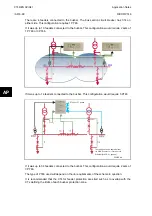
2 CT Coupler with the CB closed and Fault between a CT and the CB
P0846ENa
AP
FIGURE 21: CT’ ON BOTH SIDES OF BUS COUPLER,
CB CLOSED FAULT OCCURS BETWEEN A CT & THE CB
Treating this as a closed bus section circuit breaker the topology algorithm will have created
an overlapped zone that surrounds the circuit breaker with the bus coupler CTs as its limits
made by zone 1 and 2. This then fully replicates the scheme.
Under normal operating conditions when the circuit breaker is closed load current would flow
through the circuit breaker and hence both zones. The differential current in the two main
zones would equal zero, as the current flowing into the zones would still equal the current
flowing out.
However, if a fault was to occur in the overlapped zone, current would flow into both zones
and feed the fault. The differential current in the two main zones will be equal to that of the
fault current.
The main zones would operate. When the check zone element is calculated, the differential
current which results from the presence of the fault in the coupler, will confirm the presence
of a fault and initiate a simultaneous trip of both main.
(1) Hence, the system reacts to a fault occurring between the CT and the CB simultaneously
tripping both zones.
Zone 1
I
diff
=
I
1
+ I
2
+ I
4
=
i
diff
Z1 = i
fault
> (I
D
>2 and k2 x
I
Bias
)
Zone 2
I
diff
=
I
3
+ I
5
+ I
6
=
i
diff
Z2 = i
fault
> (I
D
>2 and k2 x
I
Bias
)
Check zone
I
diff
=
I
1
+ I
2
+ I
5
+ I
6
=
i
diff
Zx = i
fault
Содержание MiCOM P746
Страница 4: ......
Страница 5: ...Pxxx EN SS G11 SAFETY SECTION...
Страница 6: ......
Страница 8: ...Pxxx EN SS G11 Page 2 8 Safety Section BLANK PAGE...
Страница 16: ...P746 EN IT G31 Introduction MiCOM P746...
Страница 18: ...P746 EN IT G31 Introduction IT 1 2 MiCOM P746 IT BLANK PAGE...
Страница 26: ...P746 EN TD G31 Technical Data MiCOM P746...
Страница 38: ...P746 EN GS G31 Getting Started MiCOM P746...
Страница 78: ...P746 EN ST G31 Getting Started MiCOM P746...
Страница 80: ...P746 EN ST G31 Settings ST 4 2 MiCOM P746 ST BLANK PAGE...
Страница 112: ...P746 EN ST G31 Settings ST 4 34 MiCOM P746 ST BLANK PAGE...
Страница 114: ...P746 EN OP G31 Operation MiCOM P746...
Страница 136: ...P746 EN OP G31 Operation OP 5 22 MiCOM P746 OP BLANK PAGE...
Страница 138: ...P746 EN AP G31 Application Notes MiCOM P746...
Страница 142: ...P746 EN AP G31 Application Notes AP 6 4 MiCOM P746 AP BLANK PAGE...
Страница 194: ...P746 EN AP G31 Application Notes AP 6 56 MiCOM P746 AP BLANK PAGE...
Страница 196: ...P746 EN PL G31 Programmable Logic MiCOM P746...
Страница 238: ...P746 EN MR A11 Measurements and Recording MiCOM P746...
Страница 240: ...P746 EN MR A11 Measurements and Recording MR 8 2 MiCOM P746 MR BLANK PAGE...
Страница 258: ...P746 EN FD G31 Firmware Design MiCOM P746...
Страница 280: ......
Страница 342: ...P746 EN CM F21 Commissioning and Maintenance CM 10 62 MiCOM P746 CM Commissioning Engineer Customer Witness Date Date...
Страница 348: ...P746 EN MT A11 Maintenance MiCOM P746...
Страница 350: ...P746 EN MT A11 Maintenance MT 11 2 MiCOM P746 MT BLANK PAGE...
Страница 364: ...P746 EN MT A11 Maintenance MT 11 16 MiCOM P746 MT BLANK PAGE...
Страница 366: ...P746 EN TS G31 Troubleshooting MiCOM P746...
Страница 368: ...P746 EN TS G31 Troubleshooting TS 12 2 MiCOM P746 TS BLANK PAGE...
Страница 382: ...P746 EN SC G31 SCADA Communications MiCOM P746...
Страница 424: ...P746 EN SC G31 SCADA Communications SC 13 42 MiCOM P746 SC BLANK PAGE...
Страница 426: ...P746 EN SG F21 Symbols and Glossary MiCOM P746...
Страница 438: ......
Страница 440: ...P746 EN IN G31 Installation IN 15 2 MiCOM P746 IN BLANK PAGE...
Страница 465: ...Installation P746 EN IN G31 MiCOM P746 IN 15 27 IN 10P74611 1 FIGURE 18 MiCOM P746 80TE WIRING DESCRIPTION P746xxxL...
Страница 468: ......
Страница 470: ...P746 EN HI G31 Remote HMI HI 16 2 MiCOM P746 HI BLANK PAGE...
Страница 500: ...P746 EN HI G31 Remote HMI HI 16 32 MiCOM P746 HI BLANK PAGE...
Страница 502: ......
Страница 504: ...P746 EN CS A11G31 Cyber Security CS 17 2 MiCOM P746 CS BLANK PAGE...
Страница 524: ...P746 EN VH G31 Firmware and Service Manual Version History MiCOM P746...
Страница 529: ......


