


P746/EN IN/G31
Installation
(IN) 15-8
MiCOM P746
5.1 Rack
mounting
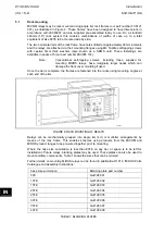
MiCOM relays may be rack mounted using single tier rack frames (our part number FX0121
001), as illustrated in Figure 2. These frames have been designed to have dimensions in
accordance with IEC60297 and are supplied pre-assembled ready to use. On a standard
483mm (19”) rack system this enables combinations of widths of case up to a total
equivalent of size 80TE to be mounted side by side.
The two horizontal rails of the rack frame have holes drilled at approximately 26mm intervals
and the relays are attached via their mounting flanges using M4 Taptite self-tapping screws
with captive 3mm thick washers (also known as a SEMS unit). These fastenings are
available in packs of 5 (our part number ZA0005 104).
Note:
Conventional self-tapping screws, including those supplied for
mounting MIDOS relays, have marginally larger heads which can
damage the front cover moulding if used.
Once the tier is complete, the frames are fastened into the racks using mounting angles at
each end of the tier.
P0147XXb
FIGURE 2: RACK MOUNTING OF RELAYS
Relays can be mechanically grouped into single tier (4U) or multi-tier arrangements by
means of the rack frame. This enables schemes using products from the MiCOM and
MiDOS product ranges to be pre-wired together prior to mounting.
Where the case size summation is less than 80TE on any tier, or space is to be left for
installation of future relays, blanking plates may be used. These plates can also be used to
mount ancillary components. Table 1 shows the sizes that can be ordered.
Further details on mounting MiDOS relays can be found in publication R7012, “MiDOS Parts
Catalogue and Assembly Instructions”.
Case size summation
Blanking plate part number
5TE GJ2128
001
10TE GJ2128
002
15TE GJ2128
003
20TE GJ2128
004
25TE GJ2128
005
30TE GJ2128
006
35TE GJ2128
007
40TE GJ2128
008
IN
TABLE 1: BLANKING PLATES
Содержание MiCOM P746
Страница 4: ......
Страница 5: ...Pxxx EN SS G11 SAFETY SECTION...
Страница 6: ......
Страница 8: ...Pxxx EN SS G11 Page 2 8 Safety Section BLANK PAGE...
Страница 16: ...P746 EN IT G31 Introduction MiCOM P746...
Страница 18: ...P746 EN IT G31 Introduction IT 1 2 MiCOM P746 IT BLANK PAGE...
Страница 26: ...P746 EN TD G31 Technical Data MiCOM P746...
Страница 38: ...P746 EN GS G31 Getting Started MiCOM P746...
Страница 78: ...P746 EN ST G31 Getting Started MiCOM P746...
Страница 80: ...P746 EN ST G31 Settings ST 4 2 MiCOM P746 ST BLANK PAGE...
Страница 112: ...P746 EN ST G31 Settings ST 4 34 MiCOM P746 ST BLANK PAGE...
Страница 114: ...P746 EN OP G31 Operation MiCOM P746...
Страница 136: ...P746 EN OP G31 Operation OP 5 22 MiCOM P746 OP BLANK PAGE...
Страница 138: ...P746 EN AP G31 Application Notes MiCOM P746...
Страница 142: ...P746 EN AP G31 Application Notes AP 6 4 MiCOM P746 AP BLANK PAGE...
Страница 194: ...P746 EN AP G31 Application Notes AP 6 56 MiCOM P746 AP BLANK PAGE...
Страница 196: ...P746 EN PL G31 Programmable Logic MiCOM P746...
Страница 238: ...P746 EN MR A11 Measurements and Recording MiCOM P746...
Страница 240: ...P746 EN MR A11 Measurements and Recording MR 8 2 MiCOM P746 MR BLANK PAGE...
Страница 258: ...P746 EN FD G31 Firmware Design MiCOM P746...
Страница 280: ......
Страница 342: ...P746 EN CM F21 Commissioning and Maintenance CM 10 62 MiCOM P746 CM Commissioning Engineer Customer Witness Date Date...
Страница 348: ...P746 EN MT A11 Maintenance MiCOM P746...
Страница 350: ...P746 EN MT A11 Maintenance MT 11 2 MiCOM P746 MT BLANK PAGE...
Страница 364: ...P746 EN MT A11 Maintenance MT 11 16 MiCOM P746 MT BLANK PAGE...
Страница 366: ...P746 EN TS G31 Troubleshooting MiCOM P746...
Страница 368: ...P746 EN TS G31 Troubleshooting TS 12 2 MiCOM P746 TS BLANK PAGE...
Страница 382: ...P746 EN SC G31 SCADA Communications MiCOM P746...
Страница 424: ...P746 EN SC G31 SCADA Communications SC 13 42 MiCOM P746 SC BLANK PAGE...
Страница 426: ...P746 EN SG F21 Symbols and Glossary MiCOM P746...
Страница 438: ......
Страница 440: ...P746 EN IN G31 Installation IN 15 2 MiCOM P746 IN BLANK PAGE...
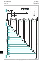
Страница 465: ...Installation P746 EN IN G31 MiCOM P746 IN 15 27 IN 10P74611 1 FIGURE 18 MiCOM P746 80TE WIRING DESCRIPTION P746xxxL...
Страница 468: ......
Страница 470: ...P746 EN HI G31 Remote HMI HI 16 2 MiCOM P746 HI BLANK PAGE...
Страница 500: ...P746 EN HI G31 Remote HMI HI 16 32 MiCOM P746 HI BLANK PAGE...
Страница 502: ......
Страница 504: ...P746 EN CS A11G31 Cyber Security CS 17 2 MiCOM P746 CS BLANK PAGE...
Страница 524: ...P746 EN VH G31 Firmware and Service Manual Version History MiCOM P746...
Страница 529: ......