Sartorius CAIS1 Скачать руководство пользователя страница 10

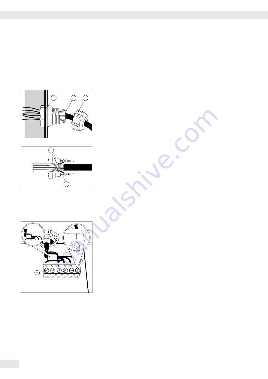
Attaching the Cable Entry


3

  Please use extreme caution when performing any work on the equipment that 

affects this cable gland.  
You must use a

 torque wrench

 to tighten the cable gland to

 5 Nm. 


4

1

5


t

    Remove the protective cap from the bore hole on the indicator.

t

   Insert the included cable gland through the bore hole and secure from the 

inside using the locknut (

1

).

2

3


t

    Insert the cable through the cable gland until the shielding (

2

) comes into 

contact with the clamps (

3

). Tighten the screw-down nut (

4

) until the 

gasket (

5

) inserted between the screw-down nut and cable forms a small 

beaded rim.

t

  Check the shielding and clamps.

t

   Securely connect the wires of the connecting cable in accordance with the 

terminal assignments.

t

   After you close the housing again, use a pressure gauge to check the 

integrity of the IP69K protection. For details, contact the Sartorius Service 
Center.

Connecting Cables


t

    Insert all cable wires through the ferrite case, wind them around the ferrite 

case and then reinsert back through the ferrite case.

t

    Screw the wires tightly into the clamps. 


See the following pages for terminal pin allocation


t

    Refer to the data sheet or operating instructions of the weighing platform 

for details on the assignment of wire colors/signals. Ensure any lines that 
are not assigned are insulated correctly.

t

    When connecting a load receptor that uses 4-conductor technology (the 

cable of the weighing platform to be connected only has 4 lines), connect 
clamp pairs 1 and 2 (EXC+ und SENSE+), and 5 and 6 (SENSE- und EXC-) 
with a wire jumper.

10 

Operating Instructions Combics Indicators


Getting Started

Содержание CAIS1

Страница 1: ...98648 018 24 Operating Instructions Sartorius Combics Series Indicator Models CAISL1 CAISL2 CAIS1 CAIS2...

Страница 2: ...imal Weighing V Combics 2 63 Weighing in Percent L Combics 2 67 Checkweighing H Combics 2 72 Classification W Combics 2 80 Totalizing s Combics 2 85 Net Total Formulation R Combics 2 89 Combining Appl...

Страница 3: ...ehr im G ltigkeitsbereich der EG Richtlinie 2009 23 EG e 1 This and similar symbols mean that the respective key should be pressed T T This means that this key must be pressed more than once t Indicat...

Страница 4: ...se electrical equipment in installations and under ambient conditions requiring higher safety standards you must comply with the provisions as specified in the applicable regulations for installation...

Страница 5: ...he IP65 IP69K protection rating is ensured only if the rubber gasket is installed and all connections are fastened securely including the caps on unused sockets Weighing platforms must be installed an...

Страница 6: ...ounting Neutral measurement Averaging animal weighing Weighing in percent Checkweighing Classification Totalizing Net total formulation Automatic initialization when the scale is switched on Automatic...

Страница 7: ...options for COM1 standard 2nd UNICOM interface for additional optional functions e g Ethernet profibus etc CAIS2 a barcode scanner can be connected via a terminal block 9 Power cord with country speci...

Страница 8: ...lt of rough handling during shipment y If you detect any damage proceed as directed in the chapter entitled Care and Maintenance under Safety Inspection t Save the original packaging for any future tr...

Страница 9: ...m Sartorius Any installation work that does not conform to the instructions in this manual results in forfeiture of all claims under the manufacturer s warranty 3 Disconnect the equipment from the pow...

Страница 10: ...e terminal assignments t After you close the housing again use a pressure gauge to check the integrity of the IP69K protection For details contact the Sartorius Service Center Connecting Cables t Inse...

Страница 11: ...ltage 6 EXC Bridge supply voltage D connection of display and control unit Interface PCB for ADC 10 000e option A10 COM1 terminal assignments see above A10 1 EXC Bridge supply voltage 2 SENSE Sense fo...

Страница 12: ...and control unit connection LED LED connection Interface PCB for RS 232 485 for IS weighing platform option A6 A7 A6 7 1 CTS 11 TxD RxD 2 DTR 12 TxD RxD 3 RxD 13 LINE_OUT 4 TxD 14 LINE_OUT 5 GND 15 G...

Страница 13: ...in 17 Control output equal Pin 18 Control output heavier Pin 19 Control output set Pin 20 Data terminal ready DTR Pin 21 Ground power supply GND Pin 22 Not assigned Pin 23 Not assigned Pin 24 Power su...

Страница 14: ...s for the cable from the indicator to an RS 232 PC interface COM1 Indicator side PC side Models CAISL1 CAISL2 DSUB connector 25 pin D Sub male connector 9 pin or 25 pin 1 Sgn GND 7 5 GND 7 GND TxD 2 2...

Страница 15: ...nstalled wall outlet which has a protective grounding conductor PE Safety Precautions 3 If you use an electrical outlet that does not have a protective grounding conductor ensure that an equivalent pr...

Страница 16: ...nerates uses and can radiate radio frequency energy and if not installed and used in accordance with these instructions may cause harmful interference to radio communications For information on the sp...

Страница 17: ...weights entered under 1 18 1 9 7 SET PREL Setting the preload 1 9 8 DEL PREL Clearing the preload 1 9 9 HND XT CAL ADJ Entering the adjustment and linearization weights 1 18 LIN WT 1 Entering the lin...

Страница 18: ...see Appendix and continue with Saving the service password k k t Access the U Code menu item t Select U Code t Enter the service password see Appendix t Apply the service password y The Service mode i...

Страница 19: ...If you return to the highest level of the Setup menu without saving the configura tion parameters beforehand menu item 11 10 any settings that have been made will be deleted The settings are made in...

Страница 20: ...rification scale interval e 11 5 2 MIN Min load 11 5 3 RANGE 1 Range 1 11 5 4 RANGE 2 Range 2 11 5 5 RANGE 3 Range 3 11 5 6 MAX Max load 11 5 7 MULT RNG Multiple range scale 11 6 e Verification scale...

Страница 21: ...the weighing capacity into a maximum of three ranges with differing readability The corresponding change takes place automatically at the defined range limits Once the scale has been tared the highest...

Страница 22: ...ired for use to zero Available weight units WT UNIT Menu item 11 7 This menu item is used to select the weighing units that have been cleared for use in weighing All units marked with a circle o have...

Страница 23: ...the display t Enter the service password see Appendix t Confirm your entry using the key y The device is in Service mode This can be recognized by the small S in the top right of the display t Select...

Страница 24: ...eographical latitude 51 00 degrees N 513 m elevation above sea level are entered the weighing equipment can be used throughout Germany Gravitational acceleration for Germany Zone D is 9 810 m s2 On de...

Страница 25: ...d When the display is activated the adjustment procedure is as follows y If the elevation and geographical latitude are used the word ALTITUD will appear briefly followed by the set elevation in meter...

Страница 26: ...he lin weight 3 1 18 4 LIN WT 4 Entering the lin weight 4 1 18 5 Function Allocation of the J Key Purpose The J key is usually used for the calibration adjustment function For detailed information abo...

Страница 27: ...l be prompted to place the first linearization weight on the platform t Place the required weight on the platform y After a short time the difference between the measured value and the true weight of...

Страница 28: ...in the Setup menu e g external calibration adjustment with default weights Setup menu item 1 9 Procedure t For scales used in legal metrology Open the menu access switch t Zero the weighing platform t...

Страница 29: ...nal function in the Setup menu e g external calibration adjustment with default weights Setup menu item 1 9 Procedure t For scales used in legal metrology Open the menu access switch t Remove the prel...

Страница 30: ...Service mode t Select the weighing platform t Enter the nominal load of the load cell s in kg under menu item 1 19 1 If the weighing platform has multiple load cells the nominal load must be multipli...

Страница 31: ...key is pressed that does not have an active operating mode function an acoustical signal double beep sounds and the message is displayed for 2 seconds The display then returns to the previous screen...

Страница 32: ...play J ISO test Start calibration or adjustment p Print key Press the key less than 2 seconds Print Press the key longer than 2 seconds Print GMP footer Keys for Combics 2 only n Toggle key When two p...

Страница 33: ...in Weighing Mode All application parameters saved e g reference values remain in memory and are available when the device has been switched off and then on again you return to the originally selected...

Страница 34: ...to prompt calibration adjustment 5 1 2 Selected weighing platform 1 or 2 6 NET B G Net Gross value on the main display with tare in memory or preset tare 7 k Identifies the value on the main display a...

Страница 35: ...in progress for Combics 2 only Menu Operating Design Switching to the Menu e t Turn on the device If it is already on turn off and then on again t During the display test briefly press the key y The m...

Страница 36: ...space Change the displayed character scroll backwards sequence Space A through Z minus sign decimal point 9 through 0 Number entry for Combics 2 Enter number values date and time etc using the 10 key...

Страница 37: ...see page 35 t Press the p key The scope of the printout depends on the position in the setup It may take several seconds Language setting Example Select the language German The factory setting for la...

Страница 38: ...menu item is displayed t Press the key to open the Setup sub menu y The first parameter in the Setup sub menu is displayed WP 1 k k t Press the k key until U CODE is displayed t Press the key to open...

Страница 39: ...settings if required or Press the key longer than 2 seconds to exit the menu Changing or Deleting Passwords t Open the U CODE menu item in the SETUP menu as described above y The old password must be...

Страница 40: ...eeds the preset minimum load is stored in the tare memory at stability The scale returns to the initial state when the load on the scale is less than 50 of the minimum load Minimum load for automatic...

Страница 41: ...ting must be activated in the menu under Setup Barcode The value is applied and saved automatically the r key does not have to be pressed Entering Identifier using a barcode scanner Combics 2 only Ide...

Страница 42: ...ight is changed menu 1 18 When the following parameters are changed Function of the q key menu item 1 9 Zero setting range menu item 1 11 Tare zero at power on menu item 1 12 The above parameters are...

Страница 43: ...tomatically using a timer under UTILIT PARAMET ER AUTO OFF menu item 8 7 Display lighting The following settings can be made for display lighting in the SETUP menu under UTILIT PARAMET ER BACKLIT on 8...

Страница 44: ...pears k t Press the k key to toggle the display y The following is displayed depending on the configuration y The gross weight in this example 170 2 g 50 g for container 120 2 g for sample Combics 1 o...

Страница 45: ...ear display test y The display for no load on the scale appears When Combics 2 is turned on it ready for weighing and zeros itself automatically With no load on the scale you can zero the weighing pla...

Страница 46: ...LCE Ser no 12345678 Vers C2 100 200810 BVers 01 62 01 End of GMP header ACE HARDWARE Headers GOETTINGEN BATCH NO 123456 Identifier 1 CUSTOMER 6 789 Identifier 2 24 08 2012 15 15 G 2250 g T 0000 g PT2...

Страница 47: ...installation location Externally connected IS scales Before use in legal metrology the scale should be calibrated via the internal calibration equipment at the installation location see the Internal C...

Страница 48: ...and the true weight of the sample will be displayed with plus minus signs Ext calibration A printout will be Nom 10000 g generated if the process Diff 1 g is cancelled using the J 4 Activate calibrat...

Страница 49: ...cale using the guidelines of your QA system He will document this setting via a Weighing module test as per USP certificate in which the measurements and min sample quantity are logged The SQmin funct...

Страница 50: ...e the sample on the scale y The minimum sample quantity is not reached symbol k p t Print the weight value N 90 0 t Place another sample on the scale y The minimum sample quantity is exceeded p t Prin...

Страница 51: ...up menu under SETUP PRTPROT menu item 7 4 The name can have a max of 20 characters Enter up to 40 characters for the value of the ID code Press the d key to activate the input mode Individual characte...

Страница 52: ...NT t Open PROTOC t Open HEADLIN k k t Select and open ID 1 k p t Enter a name for the first ID using the k and p keys or use the number block e g batch number t To save the entry press the key k t Sel...

Страница 53: ...g X Classification X Totalizing X Batching Counting to target value X Product data memory X Function Zero X X Tare X X Date time X Internal battery rechargeable Optional Optional ID codes 6 codes 40 c...

Страница 54: ...ations When you clear applications you can delete either the data stored for all applications or just selected data stored for the active application Setting Applic CLER CF menu item 3 24 Tare functio...

Страница 55: ...values 3 11 STABIL With stability 3 11 1 ACC STAB With increased stability 3 11 2 REF UPDT Reference sample updating 3 12 OFF Off 3 12 1 automat Automatic 3 12 3 REF WP Reference weighing instrument 3...

Страница 56: ...mple 17 6 The weighing platform is stable in accordance with the parameter defined for saving weights If automatic reference sample updating is selected in the menu and the piece count pcs is displaye...

Страница 57: ...be logged Configuration The Counting application is selected and printout has been set up t Place empty container on the scale t Tare the scale This is not required if the automatic tare function is...

Страница 58: ...eference sample updating is enabled Opt appears in the display p t Print results Configuring Printouts see page 96 nRef 38 pcs wRef 0 003280 kg G 0 373 kg T 0 248 kg N 0 125 kg Qnt 38 pcs 58 Operating...

Страница 59: ...eting applications When you clear applications you can delete either the data stored for all applications or just selected data stored for the active application Setting Applic CLER CF menu item 3 24...

Страница 60: ...s 3 6 3 10 digT 10 digits 3 6 4 20 digT 20 digits 3 6 5 50 digT 50 digits 3 6 6 100 diG 100 digits 3 6 7 200 diG 200 digits 3 6 8 500 diG 500 digits 3 6 9 1000 dI 1000 digits 3 6 10 RESOLUT Resolution...

Страница 61: ...The narrower the tolerance the more stable the platform is at stability The increased stability setting has a lower tolerance so that the average piece weight saves is more accurate and the results m...

Страница 62: ...latform 2 4 8 t Enter the weight of 1 meter of cable using the keypad in this example 248 g O t Save the value entered or r t Set the number of reference parts using r 1 2 5 10 20 etc O t Start the ca...

Страница 63: ...lear applications you can delete either the data stored for all applications or just selected data stored for the active application Setting Applic CLER CF menu item 3 24 Tare function If you store a...

Страница 64: ...d display until c is pressed 3 21 2 t To save the setting press the key t To exit setup Press the key several times Minimum load for initialization You can set the minimum load here i e the load that...

Страница 65: ...e when the load is less than half the minimum load The result of the most recent averaging operation is not saved If you select Display is static until the c key is pressed the calculated average rem...

Страница 66: ...in the numeric display t The averaging result is displayed p t Print the results Note If automatic printout of results is enabled you do not need to press the p key The results are printed automatical...

Страница 67: ...cations you can delete either the data stored for all applications or just selected data stored for the active application Setting Applic CLER CF menu item 3 24 Tare function If you store a tare weigh...

Страница 68: ...splay accuracy 1 decimal place 3 9 2 100FOLD Display accuracy 2 decimal places 3 9 3 DEC PLCS Decimal places in displayed result 3 10 NONE None 3 10 1 1 DEC PL 1 decimal place 3 10 2 2 DEC PL 2 decima...

Страница 69: ...e longer Setting Applic Applic 1 PERCENT SAVE WT menu item 3 11 Weighing in percent with You can use two weighing platforms simultaneously with the Weighing in Percent two weighing platforms applicati...

Страница 70: ...al to the container in accordance with reference percentage value in this example 85 g O t Start the calculation of the reference weight by pressing the O key y The calculation is based on the active...

Страница 71: ...p t Print the results Printout Configuration see page 96 pRef 20 wRef 0 085 kg G 1 080 kg T 0 675 kg N 0 423 kg Prc 100 Operating Instructions Combics Indicators 71 Operation...

Страница 72: ...value can be applied as weighed values and via relative weight limits menu item 4 5 4 Target and tolerance limits checked during input values must conform to upper limit target lower limit 1 digit Che...

Страница 73: ...viation from the target weight via the keypad The value remains valid until deleted by pressing the c key or until overwritten by a new value It remains saved after the scale is switched off Preparati...

Страница 74: ...ent is shown either as a weight value or in relation to the target Weight display The measured value line always shows the weight value even if it lies outside the tolerance range The bar graph is dis...

Страница 75: ...output set or ready for use Activation of port lines always on Activation of port lines within checkweighing range The SET output normally changes its voltage level when the load is near the target w...

Страница 76: ...on the platform O t Save the target value y The minimum symbol flashes at the top of the display 1240 t Enter lower limit value in this example 1240 g O t Save the lower limit value y The maximum symb...

Страница 77: ...lue If the weight is lighter than the target the display shows LL If the weight is heavier than the target the display shows HH Example 2 Checkweighing samples with a target weight of 1250 g and a tol...

Страница 78: ...50 g and a tolerance range from 10 g to 30 g Configuration The Checkweighing toward zero application APP ZERO is selected as well as the TAR MN MX entry and a printout has been set up see Configuratio...

Страница 79: ...you do not need to press the p key The results are printed automatically Printout configuration see page 96 Setp 1 250 kg Target Min 1 240 kg Minimum Max 1 280 kg Maximum G 1 256 kg Gross weight T 0...

Страница 80: ...applications or just selected data stored for the active application Setting Applic CLER CF menu item 3 24 Tare function If you store a tare weight value by pressing the key you can later enter a tare...

Страница 81: ...settings Factory setting MIN INIT Minimum load for initialization 3 6 1 digit 1 digit 3 6 1 2 digit 2 digits 3 6 2 5 digit 5 digits 3 6 3 10 digT 10 digits 3 6 4 20 digT 20 digits 3 6 5 50 digT 50 dig...

Страница 82: ...d value line and the current class in the number display Display of classes The current class is displayed in the measured value line Digital Input Output Interface The Classification application supp...

Страница 83: ...pplic 3 CLASS PARAM 2 CTRL SET menu item 4 3 Example 2 There should be three classes Configuration The Classification application is selected and printout has been set up O t Enter the class limits us...

Страница 84: ...c printout of results is enabled you do not need to press the p key The results are printed automatically Printout Configuration see page 96 Lim1 0 110 kg Lim2 0 130 kg G 0 118 kg T 0 000 kg N 0 118 g...

Страница 85: ...d by pressing the c key You can assign different functions to the c key for deleting applications When you clear applications you can delete either the data stored for all applications or just selecte...

Страница 86: ...r settings Factory setting MIN INIT Minimum load for initialization 3 6 1 digit 1 digit 3 6 1 2 digit 2 digits 3 6 2 5 digit 5 digits 3 6 3 10 digT 10 digits 3 6 4 20 digT 20 digits 3 6 5 50 digT 50 d...

Страница 87: ...lue in totalizing memory G 0 250 kg y Item is printed automatically component log T 0 000 kg N 0 250 kg n 1 y The transaction counter value is increased by one to 1 t Remove the first weight from the...

Страница 88: ...oggle the display between individual value and total c t End totalizing G 1 346 kg y Configured total data record is printed T 0 346 kg N 1 000 kg n 2 88 Operating Instructions Combics Indicators Oper...

Страница 89: ...item is selected the entire component record is printed If the 3 17 3 menu item is selected the following items are generated only once for the first component if they have been configured Blank line...

Страница 90: ...kes it possible to toggle from the small component platform to the large component platform during measurement Once you toggle to the large component platform the and keys are available until a compon...

Страница 91: ...platform is tared and the component counter value is increased by one The prompt to fill and save the second component is now displayed t Place the second component into the container in this example...

Страница 92: ...ent using the O key Cmp003 0 375 kg yThe component record is printed automatically y The component counter value is increased by one The prompt to fill and save the fourth component is now displayed c...

Страница 93: ...g Animal Weighing Checkweighing Animal Weighing Classification Weighing in Percent Totalizing Weighing in Percent Checkweighing Totalizing Weighing in Percent Checkweighing Weighing in Percent Classif...

Страница 94: ...29 Reduce the minimum load setting or increase the reference sample quantity setting and the number of parts in the container D t Toggle to Checkweighing O t Start Checkweighing 1 0 0 t Enter target v...

Страница 95: ...operations as desired w t Toggle display from individual value to total c t End the portioning options and print the final evaluation Configured printout Total nRef 10 pcs wRef 0 001000 kg Setp 100 p...

Страница 96: ...Setting Applic Applic 3 TOTALIZ printout component printout Print totalizing printout Combics 2 only For selected application Totalizing Net total formulation with c key When switching to another appl...

Страница 97: ...elect print items Press the k key t Save the desired print items Press the key t Press the key to switch to the active print selection The selection bar appears on the left The required print item is...

Страница 98: ...Press the k key until 7 6 appears in the display t Press the key y The list of print items appears t Press the key to go to the selection list blank y The first print item of the selection list is di...

Страница 99: ...can now select additional print items in the same way t To exit print item entry press the key until APPLIC appears in the display t Press and hold the key 2 3 sec to switch to weighing mode t Carry...

Страница 100: ...in 2 seconds Saving preset tare values t Allocate preset tare memory t Enter a memory number and press and hold the t key min 2 seconds Activating saved product or tare values t Enter a memory number...

Страница 101: ...he k key to switch between wRef average piece weight and nRef quantity Use the key to scroll the displayed value to the right Use the R key to activate the displayed memory Press and hold the c key mi...

Страница 102: ...torius equipment Check the pin assignment against the cabling diagrams and disconnect any lines that are not assigned Failure to do so may cause malfunction damage or even completely ruin your indicat...

Страница 103: ...COM1 Foot Hand switch PC RS 232 interface 2nd weighing platform Combics 2 only RS 232 interface External checkweighing display stop light via a digital I O Sartorius standard The following devices can...

Страница 104: ...ther e g data transfer and control via a PC using the optional UniCOM interface with simultaneous printing via the COM1 printer interface During data communication each interface can use a different p...

Страница 105: ...ot see page 96 Configuring Printouts If you do not activate and configure a user definable data record the printout simply contains the current value displayed on the display and control unit weight w...

Страница 106: ...Trigger c key function Combics 2 only kF3_ F3 Trigger r key function Combics 2 only kF4_ F4 Trigger O key function Combics 2 only kF5_ F5 Trigger w key function Combics 2 only kF6_ F6 Trigger I key f...

Страница 107: ...spaces Values with no decimal point are output without a decimal point Data Output Format with 16 Characters without Data Header Normal Operation Position 1 2 3 4 5 6 7 8 9 10 11 12 13 14 15 16 A A A...

Страница 108: ...s Normal Operation 1 2 3 4 5 6 7 8 9 10 11 12 13 14 15 16 17 18 19 20 21 22 K K K K K K A A A A A A A A A E E E CR LF K K K K K K A A A A A A A A A E E E CR LF CR LF K ID code character right justifie...

Страница 109: ...pace Number 2 or 3 digit error number G Gross value N Net value T Application tare memory 1 T2 Application tare memory 2 Diff Difference from calibration value Targ Exact adjustment weight value Nom E...

Страница 110: ...inter Port PRINTER You can connect one or two strip printers or one or two label printers to the Combics Configure the COM1 and UniCOM interfaces as printer ports in the Printer menu item There are se...

Страница 111: ...footer is printed either after each individual measurement result GMP compliant printout always for 1 result menu item 7 13 2 or after the last result in a series of measurements GMP compliant printou...

Страница 112: ...type Ser no 12345678 Combics serial no Vers C2 100 280810 Software version of application BVers 01 62 01 Software version of basic version Type IS12000S Platform type Ser No 12345678 Platform serial n...

Страница 113: ...e header lines refer to the chapter of the respective application Weighing application If selected an empty line will be printed HEADER LINE1 HEADER LINE2 14 01 2012 09 43 G 1 402 kg T 0 200 kg N 1 20...

Страница 114: ...345678 Vers C2 100 280810 BVers 01 62 01 Linearization Wt 1 7 00 kg Wt 2 15 00 kg Wt 3 22 00 kg Wt 4 30 00 kg completed 14 01 2012 13 02 Name Calibration adjustment printout 14 01 2012 13 50 Type CAIS...

Страница 115: ...n was not met Do not carry out adjustment until after 0 display e g not tared or weighing pan loaded Unload scale tare using the key inf 03 Adjustment could not be completed within a certain time Allo...

Страница 116: ...h all its connectors 2 Do not open the indicator while it is carrying current Wait at least 10 seconds after disconnecting it from power before beginning to open the equipment Proper fitting of all su...

Страница 117: ...device is no longer ensured when The device or the mains connecting lead shows visible damage The integrated power supply for the indicator no longer functions properly The device has been stored for...

Страница 118: ...by local public disposal operations not even by small commercial operators For disposal in Germany and in the other member nations of the European Economic Area EEA please contact our local service te...

Страница 119: ...nd 0 3 1 12 V e Fraction of tolerance for this module for Delta Umin 0 672 V e 0 5 for Delta Umin 1 12 V e 0 3 Measuring signal 0 mV to 27 7 mV Measuring signal variation 4 2 mV to 27 7 mV Sensitivity...

Страница 120: ...e for Pind 0 3 0 546 V e Fraction of tolerance for this module for Delta Umin 0 328 V e 0 5 for Delta Umin 0 546 V e 0 3 Measuring signal 0 mV to 24 6 mV Measuring signal variation 3 28 mV to 24 6 mV...

Страница 121: ...Operating Instructions Combics Indicators 121 Device Dimensions All dimensions are given in millimeters Device Dimensions...

Страница 122: ...apter cable for CAISL indicator YCC01 01CISLM3 Adapter cable for CAIS indicator YCC02 R12F6 Ink ribbon for YDP14IS 0CEUVTH 69Y03234 3 paper rolls for YDP04IS 60 mm 75 m thermal paper 69Y03090 Labels s...

Страница 123: ...or Windows YSW03 SartoCollect YSC02 Other functions Guard covers x2 YDC01CI IP65 kit for cable connections D SUB 25 on request Cable gland for cables with diameter 4 5 to 9 mm M16 x 1 5 YAS04CIS Kit f...

Страница 124: ...le with cable gland open cable ends on Combics side for barcode scanner YBR03FC 5 pin DIN socket 1m YCC02 BR02 for printer YDP12 04IS 9 pin D SUB plug 6 m YCC02 D09M6 for printer YDP20 0CE or PC 9 pin...

Страница 125: ...til the end of the calendar year after next If the scale is used for fill level control in accordance with legislation on prepackaging verification is valid until the end of the following calendar yea...

Страница 126: ...126 Operating Instructions Combics Indicators Declarations of Conformity Declaration of Conformity...

Страница 127: ...Operating Instructions Combics Indicators 127 Declarations of Conformity...

Страница 128: ...128 Operating Instructions Combics Indicators Declarations of Conformity...

Страница 129: ...Operating Instructions Combics Indicators 129 Declarations of Conformity...

Страница 130: ...130 Operating Instructions Combics Indicators Test Certificate...

Страница 131: ...Operating Instructions Combics Indicators 131 Plates and Markings...

Страница 132: ...132 Operating Instructions Combics Indicators Plates and Markings...

Страница 133: ...Operating Instructions Combics Indicators 133 Plates and Markings...

Страница 134: ...134 Operating Instructions Combics Indicators Plates and Markings...

Страница 135: ...ser requirements see page 140 wp1 Settings for weighing platform 1 com1 Settings for the RS 232 interface unicom Settings for the 2nd optional interface com wp 10 000e ADC setting CTRL IO Universal in...

Страница 136: ...9 1 1 NO No retain user defined settings 9 1 2 Combics 2 application menu Factory setting Applic Applic 1 WEIGH Weighing min init Minimum load for automatic taring 3 5 1 digit 1 digit 3 5 1 2 digit 2...

Страница 137: ...min init Minimum load for application 3 6 1 digit 1 digit 3 6 1 2 digit 2 digits 3 6 2 see Weighing 1000 DI 1000 digits 3 6 10 start Start averaging 3 18 MANUAL Manual 3 18 1 AUTOMAT Automatic 3 18 2...

Страница 138: ...CHECK RG On within checkweighing range 4 4 4 STAB CHK On at stability within checkweighing range 4 4 5 INPUT Parameter input 4 5 TAR MN MX Min Max target value 4 5 1 TARG PER Only target value with pe...

Страница 139: ...once with the O key 3 17 3 VAL FROM Value source for automatic saving 3 22 Appl 1 Application 1 3 22 1 Appl 2 Application 2 3 22 2 SAV VAL Save value 3 23 NET Net 3 23 1 CALCUL Calculated 3 23 2 NET...

Страница 140: ...Filling mode 1 2 2 REDUC Low filtering 1 2 3 OFF Without filtering 1 2 4 STAB RNG Stability range 1 3 MAX ACC Maximum accuracy 1 4 digit 1 3 1 V ACC Very accurate 1 2 digit 1 3 2 ACC Accurate 1 digit...

Страница 141: ...Calibration with manual adjustment 1 10 2 ZERORNG Zero range 1 11 1 PERC 1 percent max load 1 11 1 2 PERC 2 percent max load 1 11 2 5 PERC 5 percent max load 1 11 3 INIT ZER Zero at Power On 1 12 1 P...

Страница 142: ...rvals 3 2 15 DIV 1 Increase resolution by 1 scale interval 3 2 16 setup WP 1 intern Reset Factory settings WT PARA Restore factory default settings 9 1 NO No 9 1 1 YES Yes 9 1 2 setup WP 1 intern ADC...

Страница 143: ...nual without stability 6 1 1 IND AFTR Manual after stability 6 1 2 AUT W O Automatic without stability 6 1 4 AUT WITH Automatic with stability 6 1 5 PROT PRN Protocol printout for computer PC 6 1 7 AU...

Страница 144: ...e 1 character after CTS 5 4 3 YDP14IS LINE Strip printer LABEL Label printer Universal printer CONFIG BAUD Baud rate 5 1 150 150 5 1 1 300 300 5 1 2 600 600 5 1 3 1200 1200 5 1 4 2400 2400 5 1 5 4800...

Страница 145: ...BI standard version Menus 5 1 to 9 1 same as for COM1 XBPI 232 XBPI 232 XBPI 485 XBPI 485 0 to 31 Network address selectable from 0 to 31 SMA SMA interface function Menus 5 1 to 5 6 same as for COM1 p...

Страница 146: ...04IS YDP04IS LINE Strip printer label Label printer lab ff Label printer with manual feed Analog Analog data output port for PLC operation Analog output value 8 12 NET Net value 8 12 1 GROSS Gross val...

Страница 147: ...19 PRINT Trigger p key function 8 19 1 see 8 4 B G NET Trigger L key function Combics 2 only 8 19 15 4 extern External control input 4 8 20 PRINT Trigger p key function 8 20 1 see 8 4 B G NET Trigger...

Страница 148: ...d 7 71 TOTAL 1 Totalizing results user defined 7 81 QTY 2 Printout quantity to UniCOM 7 9 1 PRNT O 1 printout 7 9 1 2 PRNT O 2 printouts 7 9 2 INDIV 2 Single and results printout for all other applica...

Страница 149: ...r see 8 9 8 8 3 timer Timer for automatic shutoff 8 9 1 1 Min After 1 minute warning displayed for 1 minute then off 8 9 1 2 2 Min After 2 minutes warning displayed for 2 minutes then off 8 9 2 5 5 Mi...

Страница 150: ...hing platform 51 53 Geographic latitude in degrees 151 Geographic altitude in meters 9 81 Acceleration of gravity m s2 then however no latitude and altitude switch Menu access switch info WP 2 2nd wei...

Страница 151: ...kg 11 7 4 t Tons t 11 7 21 lb Pound ounces lb oz 11 7 22 CAL UNIT Calibration Adjustment unit 11 8 FREE User defined o 11 8 1 g Grams g 11 8 2 kg Kilograms kg 11 8 3 t Tons t 11 8 21 SAVE Save configu...

Страница 152: ...Tons t 11 7 21 lb Pound ounces lb oz 11 7 22 CAL UNIT Calibration Adjustment unit 11 8 FREE User defined o 11 8 1 g Grams g 11 8 2 kg Kilograms kg 11 8 3 t Tons t 11 8 21 SAVE Save configuration para...

Страница 153: ...claration of conformity 126 Deleting the preload 29 Device functions 53 Device information 150 Device parameters 37 43 Device parameters overview 135 Dimensions 121 Display lighting 43 Display modes 3...

Страница 154: ...tting parameters 21 Configuration 23 Setting the preload 28 Setting the time 149 Setting up password protection 38 Shutoff automatic 43 SMA communication 105 Technical data 119 Totalizing 85 Type appr...

Страница 155: ...Operating Instructions Combics Indicators 155 Appendix Guide to verification...

Страница 156: ...or are available please click on the appropriate links Start t Click on Start the Excel Program y The Excel file automatically opens with the Excel program MS Excel must already be installed on your c...

Страница 157: ...tical order a to Z then the characters and then numbers in descending order 9 to 0 k or p key multiple times t Press the k or p keys until the desired character is displayed t Confirm the displayed ch...

Страница 158: ...158 Operating Instructions Combics Indicators...

Страница 159: ...Operating Instructions Combics Indicators 159...

Страница 160: ...from the connected device to the indicator complete scale These devices may also be installed in Zone 2 or Zone 22 if they are suitable for Category 3 as per the ATEX Directive Gas Group IIC temperatu...

Страница 161: ...ding conductor Equipotential bonding conductor Indicator CAIS with option Y2 Analog weighing platforms load cells of series CAAP Option Y2 Connection alternatives Explosion safe area Note 8 Note 8 Not...

Страница 162: ...external connecting cables firmly to avoid damage and strain The cable connections inside the explosion risk area must be secured against loosening 8 All metal parts must be electrically connected to...

Страница 163: ...box are only suitable for fixed placement and must be laid fixed Otherwise use screwed connections designed according to EN60079 0 and rounded at an angle of 75 minimum and a radius at least equal to...

Страница 164: ...s without the prior writ ten permission of Sartorius All rights reserved The status of the information specifications and illustrations in this manual is indicated by the date given below Sartorius re...

Отзывы: