27
■
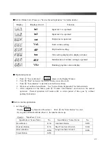
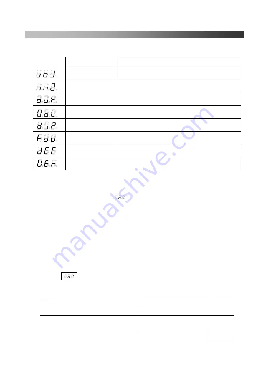
Service Menu List
(Please see “Service Menu Explanation” for further details.)
Display
Displayed word
Function
in1
Input test 1 is operated.
in2
Input test 2 is operated.
out
Output test is operated.
VoL
Each volume setting.
diP
Dip function setting.
tou
Time setting displayed in display window.
dEF
Initialization of volume setting is operated.
VEr
Running program version display.
■
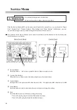
Operation process
1.
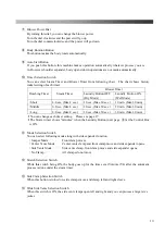
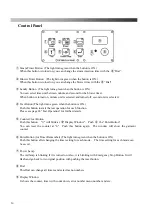
Push
①
“Service Button”.
→
shows on the Display Window.
2.
Turn
⑤
”Dial” and select the Service Menu you want to work.
3.
Push
④
”Enter Button” to start the selected Service Menu.
4.
Work or set on the selected Menu. See “Service Menu Explanation” for further details.
5.
After completion of the Menu, push
②
“Counter Clear Button”, and return to the normal
operation. (Normal operation will resume after a certain period of time goes by without
pushing this button.)
■
Service menu explanation
1.
in1 (Input Test 1)
・
Display by Operation Procedure 1. Push
④
the “Enter Button” to select.
・
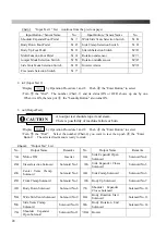
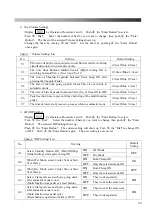
If you push each Button/Pedal (Chart-1), the number shows up.
Chart-1
“Input Test 1” List
Input Button
/
Sensor Name
No.
Input Button
/
Sensor Name
No.
Reset Button
b1A
Auto Start Button
b2C
Rotation Button
b1b
Short Time Select Switch
b4A
Blower Button
b2A
Long Time Select Switch
b4b
Steam Button
b2b
Содержание DF-100E-V3
Страница 40: ...40 ...
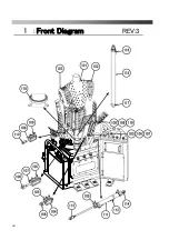
Страница 42: ...42 Front Diagram 1 Front Diagram REV 3 ...
Страница 44: ...44 Rear Diagram 2 Rear Diagram REV 3 ...
Страница 46: ...46 Switch Solenoid Valve Diagram 3 Switch Solenoid Valve Diagram REV 3 315 301 ...
Страница 48: ...48 Switch Solenoid Valve Diagram 3 Switch Solenoid Valve Diagram REV 3 315 301 ...
Страница 50: ...50 Steam Piping Diagram 4 Steam Piping Diagram REV 3 ...
Страница 52: ...52 Cover Diagram 5 Cover Diagram REV 3 513 ...
Страница 56: ......
Страница 57: ......
Страница 58: ......
Страница 59: ......
Страница 61: ......
Страница 62: ...DF 100E V3 Rev 6 2019 1 ...

