background image

A

A

B

B

C

C

D

D

E

E

4

4

3

3

2

2

1

1

Title

Size

Document Number

Rev

Create:

Sheet         of 

Category

Mod:

Tuesday, April 28, 1998

82005-10

C

NAV-1 / ARINC-429 GPS  (INT RELAY)

Vista, Ca.

B

23

29

SN3500 INSTALLATION DRAWING

Sunday, December 09, 2007

Title

Size

Document Number

Rev

Create:

Sheet         of 

Category

Mod:

Tuesday, April 28, 1998

82005-10

C

NAV-1 / ARINC-429 GPS  (INT RELAY)

Vista, Ca.

B

23

29

SN3500 INSTALLATION DRAWING

Sunday, December 09, 2007

Title

Size

Document Number

Rev

Create:

Sheet         of 

Category

Mod:

Tuesday, April 28, 1998

82005-10

C

NAV-1 / ARINC-429 GPS  (INT RELAY)

Vista, Ca.

B

23

29

SN3500 INSTALLATION DRAWING

Sunday, December 09, 2007

GPS SELECTED

4

ACFT PWR

ARM SELECT

APPR ARM OUT

OBS CMND OUT

LEG/OBS- CTRL

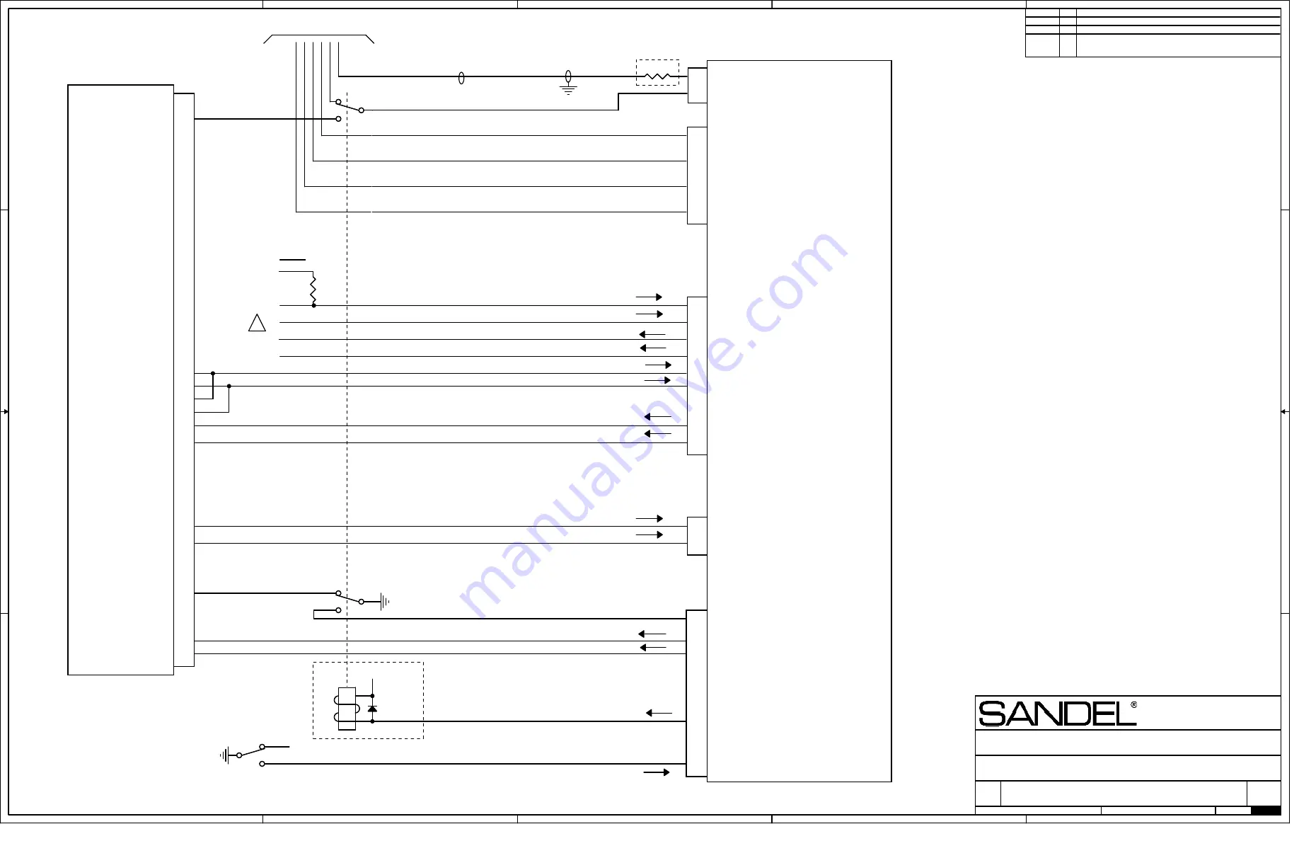
NAV-1 AND ARINC 429 GPS INTERCONNECT.

KLN90-B SHOWN FOR REFERENCE

GPS1 RELAY

7

15 GPS2 RELAY

MASTER MODE

SLAVE MODE

GPS ENABLED FROM
SWITCH/ANNUNCIATOR UNIT.
(SLAVE MODE ONLY)

429-1 TX-A

1

N/C

VERT -FLAG

H

TO VHF NAV
RECEIVER
RESOLVER
INTERCONNECT

OBS RESOLVER E/F (VREF) (IN)

OBS RESOLVER COS OUT

GPS/LORAN RECEIVER. 
KLN-90B SHOWN FOR
REFERENCE

OBS RESOLVER H (IN)

2

!

F

E

APPR ACTIVE
SEE NOTE 2

P2

GPS DISPLAYED

429-1 RX-B

NOTE 7

VERT +UP

CO

MPO

S

IT

E

ARINC 429 RX-B

10

NOTE 1

VERT +DOWN

ARINC 429 TX-B

VERT +FLAG

D

SN3500

16

OBS RESOLVER SIN OUT

ARINC 429 RX-A

429-1 TX-B

ARINC 429 TX-A

G

P901

FROM VHF NAV RECEIVER

GPS SWITCHING RELAY CONNECTIONS  (SEE NOTE 3)
CONNECT P3-4 OR P3-7 BUT NOT BOTH.

LRN APPR IN

14

P1

44 LRN APPR ARM IN

APPR ACTIVE

16

17

NOTE 6

ARINC 429 RX-A

ARINC 429 RX-B

JUMPERS REQUIRED IF NO
AIRDATA COMPUTER
INSTALLED.

A

INITIAL RELEASE

DATE

REV COMMENTS

C

NOTES:

1.  CONNECT OBS "H" FROM RECEIVER "H" or "C" WHICHEVER IS THE ACTIVE
OUTPUT.  CHECK APPROPRIATE NAV RECEIVER SCHEMATICS.   CONNECT
"SIN OUT" and "COS OUT" TO THE ACTIVE RETURN PINS, USUALLY D/F. 
CONNECT "OBS VREF" TO EITHER STATOR RETURN PIN (REF OR GROUND)
USUALLY E or G.  THE LOAD RESISTOR SIMULATES A SYNCHRO.

4.  CHECK MANUFACTURERS DOCUMENTATION FOR ANY ADDITIONAL
INSTALLATION SPECIFIC RELAY POLES WHICH MAY ALSO BE
NEEDED.

2.  THE APPROACH ACTIVE OUTPUT FROM THE GPS TO THE AUTOPILOT MAY
HAVE TO BE AN ADDITIONAL RELAY.  SEE THE MANUFACTURERS
INSTALLATION DIAGRAMS.

5.  KLN-90B PINOUTS SHOWN.  CERTAIN CONNECTIONS SUCH AS
GPS_DISPLAYED AND OBS/LEG ARE SPECIFIC TO KLN-90B.

7.  FOR 3V COMPOSITE NAV SOURCES INSERT A 470K SERIES RESISTOR
LOCATED AT THE SN3500 CONNECTOR.  NOT REQUIRED FOR .5V
SOURCE.

1   MASTER:  SN3500 CONTROLS THE NAV/GPS SWITCHING (PREFERRED)
2   SLAVE:   EXTERNAL NAV/GPS SWITCH CONTROLS THE SN3500

3.  THE PREFERRED INSTALLATION IS THE SN3500 P3-7 CONTROLLING AN
EXTERNAL SWITCHING RELAY.  IF AN EXISTING SWITCH CONTROL BOX IS
INSTALLED AND IT IS DESIRED TO LEAVE IT OPERATIONAL, USE P3-4 TO
SENSE GPS MODE AND SELECT SLAVE FOR THE MODE SETTING ON THE
OBS/RELAY/CDI MAINTENANCE PAGE.

6.  MSG AND WPT ANNUNCIATORS ARE COMMUNICATED ON THE ARINC 429
SERIAL CHANNEL.

RELAY SENSE NOTE 8

4

GPS1 SENSE

COMPUTER CONTROLLED DRAWING
DO NOT REVISE MANUALLY

6

22

7

36

18

3

8

23

37

38

GS - Flag

GS + Flag

GS + Up

GS + Down

Composite 1 In

APPR ARM

IN SLAVE MODE THE
RELAY DRIVE  IS PART
OF THE EXTERNAL
SWITCH/ANNUNCIATOR
UNIT

ILS1 ENERGIZE

ILS ENERGIZE

KLN90-B SHOWN

SEE NOTE 5

P1

P2

P3

30
33

429-1 RX-A

5

4

30

15

31

17

9

8

24
23

A1

A/R 780 MINOR DOC CHANGES

8.  ONLY USED WHEN SN3500 IS IN MASTER MODE.  SELECT GPS1 FOR
SENSE ON OBS/RELAY/CDI MAINTENANCE PAGE.

THIS DIAGRAM SHOWS USE OF INTERNAL NAV CONVERTER AND
DEVIATION RELAY OF SN3500

C

A/R 806 429 TX OUT PIN CORRECTIONS,
P1-22 AND P1-7 REVERSED.


470K


470K

1N4004

1N4004


220 O

hm  

220 O

hm

K1

K1

Содержание SN3500

Страница 1: ...82005 IM K SN3500 Primary Navigation Display Installation Manual Sandel Avionics Inc 2401 Dogwood Way Vista CA 92081 Phone 760 727 4900 FAX 760 727 4899 Website www sandel com Email support sandel com...

Страница 2: ...82005 IM K Sandel SN3500 Installation Manual Page ii This page intentionally left blank...

Страница 3: ...INC Channels 1 7 1 4 10 DME Interface 1 7 1 4 11 Special Considerations for GARMIN GNS430 530 Series 1 7 1 4 12 Special Considerations for UPS GXXX 1 8 1 4 13 Brightness Control 1 8 1 4 14 Traffic 1 8...

Страница 4: ...onnector P 1 Pinout Description 3 4 3 3 2 Connector P 2 Pinout Descriptions 3 7 3 3 3 Connector P 3 Pinout Descriptions 3 10 4 Setup Procedures 4 1 4 1 General 4 1 4 2 Accessing the Maintenance Menus...

Страница 5: ...10 BRG Source Selection 11 6 11 1 11 DME Selection 11 6 11 1 12 GPS Interface and Control 11 7 11 1 13 Marker Beacon Interface 11 8 11 1 14 Flight Control System Interface 11 9 11 1 15 Stormscope Inte...

Страница 6: ...Following sections renumbered Section 12 DWG 82005 10 sheet 41 I N A Intentionally skipped H 8 24 09 Updated for software version 4 01 AR1087 Section 3 3 1 change inverter range from 360 440Hz to 240...

Страница 7: ...fy pin description P2 28 P2 13 Clarify composite input connection with analog NAVs Page 3 9 Clarify P2 10 HDG CRS Excitation connection when not connected Page 5 1 Added reference to 82005 PG SN3500 P...

Страница 8: ...82005 IM K Sandel SN3500 Installation Manual Page viii Revision Date Comments A1 04 21 2005 A R 780 minor doc and dwg changes A 03 31 2005 Initial release...

Страница 9: ...f the Department of State in accordance with the International Traffic in Arms Regulations ITAR 22 CFR 120 130 It may not be exported sent transferred disclosed or otherwise released to a foreign pers...

Страница 10: ...ility 1 3 Installation Planning Sandel Avionics has taken many equipment interface possibilities into consideration during the design of the SN3500 to ensure maximum interoperability with other avioni...

Страница 11: ...re the correct orientation and positioning of the three SN3500 D connectors The connector numbers are printed on the back of the SN3500 for reference 2 Review special items such as connection of the N...

Страница 12: ...rmed using the SN3500 Compass maintenance page The SN3500 will provide standby heading operation from the flux gate alone in the event of directional gyro DG failure The SN3500 has a 3 wire ARINC 407...

Страница 13: ...for annunciation or AFCS reverse course control when required This operates during LOC operation when the aircraft is flying with the tail of the Course Pointer up For older Century autopilots a Datu...

Страница 14: ...uidance is used to drive the ILS Energize pin during GPS operation In this situation NAV1 GPS1 use ILS Energize 1 and NAV2 GPS 2 use ILS Energize 2 to display vertical guidance For analog receivers tw...

Страница 15: ...municating with ARINC 429 ARINC 419 RS232 and Analog All equipment capable of ARINC compatibility such as GPS FMS Navigation Traffic etc can be directly connected to the appropriate signal input There...

Страница 16: ...gs VDI Flags if enabled on Sandel Annunciators 1 4 13 Brightness Control Brightness control is internal through a pilot s menu No external brightness buss is used 1 4 14 Traffic The SN3500 supports Tr...

Страница 17: ...ole display the WSI receiver RS 232 interface must be configured as NO FLOW CONTROL see the WSI receiver manual for details regarding receiver configuration 1 4 16 TACAN The SN3500 supports TACAN inpu...

Страница 18: ...and lateral acceleration data via Arinc 429 An optional key code is required to enable this feature See the Reversionary Control interface drawing in this manual for interface wiring requirements This...

Страница 19: ...third inverter input Datum Excitation is available specifically used in situations where the autopilot uses an additional inverter or the autopilot inverter frequency is higher than 400Hz The followin...

Страница 20: ...N DD44F10JVLO 2 60144 Shim Flush Mounting 1 61062 3ATI Mounting Clamp 1 82005 IM Installation Manual SN3500 1 88114 USB Cable 1 2 3 Approval Summary 2 3 1 License Requirements None 2 3 2 Approval Dat...

Страница 21: ...e either on or within a specific type or class of aircraft to determine that the aircraft installation conditions are within the TSO standard TSO articles must have separate approval for installation...

Страница 22: ...3500 is to be installed The environmental category for the SN3500 should be stipulated on the FAA Form 337 or other approval form A Functional Ground Test Procedures Report and an Operational Flight C...

Страница 23: ...on units with serial number 5 2500 or higher 27 5 Vdc 1 4A nominal 38 5 watts Lamp Units 27 5 Vdc 1 2A nominal 33 watts LED Units 14 0 Vdc 2 4A nominal 33 watts LED Units 2 5 Connector Summary The SN...

Страница 24: ...Z grounded Stepper A Bendix King stepper Phase A 33 Hdg1B In A429 B side 429 A407 Synchro Y Z grounded Stepper C Bendix King stepper phase C 19 Hdg1 Valid In Discrete Valid Hdg Analog Note Not used w...

Страница 25: ...pin 23 Flag Note For use with external SUPERFLAG see installation drawing for series resistor required 23 LAT1 LL Flag In In Differential pair to pin 37 Flag 8 LAT1 LL Dev In FLY RIGHT In Differential...

Страница 26: ...RS232TxD Out R232 43 WPT In Discrete 29 MSG In Discrete 14 ACT In Discrete 44 ARM In Discrete 30 Audio LL Out Out Audio LL Low Level Audio output requires external amplifier future provision not curre...

Страница 27: ...dc 3 NAV1A In A429 A side 429 A407 Synchro X Z grounded A710 Composite Video 33 NAV1B In A429 B side 429 A407 Synchro Y Z grounded 19 ILS Energize2 Discrete In In Discrete Valid Discrete Open Gnd or O...

Страница 28: ...ef In Resolver DC 23 OBS Resolver H In Resolver H 8 OBS Resolver X Sin out Out Resolver Out 38 OBS Resolver Y Cos out Out Resolver Out 24 Fluxgate Excitation In Fluxgate Excitation 9 Fluxgate X In 39...

Страница 29: ...Flag Out LL Out gnd ref 28 FCS Lat Dev RIGHT Out LL Out gnd ref 13 FCS Vert Dev UP Out LL Out gnd ref 43 FCS Lat Superflag Out Out Superflag Out 29 FCS Vert Superflag Out Out Superflag Out 14 RS232 2...

Страница 30: ...ut Out Open Drain 3 Aircraft Ground In System Ground 11 Aircraft Ground In System Ground 4 GPS1 Relay Sense Selected In Discrete Valid 12 GPS2 Relay Sense In Discrete Valid 5 NAV2 Relay Sense In Discr...

Страница 31: ...rms 20 100Vdc 100K ADF_REF 10Vdc 50 60Vdc 100K Alt DC Coarse 0 to 15Vdc 100Vdc 100K Analog DME 0 to 8Vdc 75VdcNote 5 180K Discrete Valid High 14 0VdcNote 4 60Vdc 500K Discrete Valid Low 3 5Vdc Note 4...

Страница 32: ...to power supply may cause damage to components 4 Discrete inputs actively pulled to 27 5v through 30k ohms when selected active low or actively pulled to 0v through 30k ohms when selected active high...

Страница 33: ...oll 332 Lateral Acceleration 350 Maintenance Words Sandel SG102 Only 351 Maintenance Words Sandel SG102 Only 352 Maintenance Words Sandel SG102 Only 353 Maintenance Words Sandel SG102 Only 354 Mainten...

Страница 34: ...MA 266 FMC Nav Mode 275 Status Word GAMA 310 Present Position Latitude 311 Present Position Longitude 312 Ground Speed 313 Track Angle True 326 Lateral Scale Factor 327 Vertical Scale Factor 377 Equip...

Страница 35: ...0 Installation Manual Page 2 17 2 6 2 ARINC 419 429 Serial Transmitter Interfaces The SN3500 is capable of transmitting the following low or high speed ARINC 429 data LABEL DESCRIPTION 100G Selected C...

Страница 36: ...g agency and existing conditions as to unit location and type of installation However the following considerations should be heeded before installing the SN3500 Close adherence to these considerations...

Страница 37: ...zes and types and subscribe to appropriate FAR Parts 23 25 27 and 29 as well as AC 43 13 1 and 2 B The use of MIL C 27500 shielded wire and MIL W 22759 single conductor wire is recommended The use of...

Страница 38: ...es of at least the recommended size are installed in accordance with the installation drawings and these wires are connected to a bonded aircraft ground Ensure that shielded wiring is used to the Flux...

Страница 39: ...0 Hz minimum Input impedance is 220K 24 AWG shielded wire is recommended for this function P1 31 TCAS 429 A P1 17 TCAS 429 B Optional ARINC 429 input for traffic P1 2 Data link A P1 32 Data link B Opt...

Страница 40: ...37 VOR LOC FLAG P1 23 VOR LOC FLAG Used when an external NAV converter or analog output GPS is used Differential Low level NAV Flag inputs Superflags are supported with a series resistor see the insta...

Страница 41: ...ceivers are compatible as shown on the installation drawings Some very old designs may use transformer outputs which are AC coupled These may not be compatible P1 42 ARINC1 429 A Output P1 28 ARINC1 4...

Страница 42: ...2 Gnd P2 32 GPS2 FMS 2 429B 422 232 Signal Main input from GPS FMS 2 P2 18 VHF Nav 1 ILS Energize Input This pin controls the Vertical Deviation Bar when selected to NAV1 These signals also control th...

Страница 43: ...fic LOC input 24 AWG shielded wire is recommended for these connections Note When using the composite signal for the localizer deviation input the calibration procedure found in section 7 1 5 must be...

Страница 44: ...shielded triple conductor is recommended for these signals P2 10 HDG CRS Datum Excitation This is a ground referenced 400 5Khz excitation input for the HDG Datum and CRS Datum outputs only This input...

Страница 45: ...ed course and selected heading for ARINC 429 Long Range NAV receivers 24 AWG twisted shielded pair wire is required for these functions 3 3 3 Connector P 3 Pinout Descriptions P3 1 P3 9 Display Primar...

Страница 46: ...rnal toggle switch or maintained pushbutton switch P3 7 GPS1 Switching Relay Discrete Output Can be used to operate a switching relay whenever GPS1 or Loran1 is selected by the NAV pushbutton The rece...

Страница 47: ...ck Course Discrete Output Open Drain Used to feed the back course sensing input of an AFCS When the Course Select rotates either direction passing 90 clockwise or counterclockwise from the lubber line...

Страница 48: ...us cannot be called up accidentally during flight B Once the Maintenance Menu is entered press the NEXT or PREV softkeys to cycle the MAINTENANCE MENU pages Use the UP DOWN arrow keys for selections a...

Страница 49: ...SN3500 refer to the Pilot s Guide for the SN3500 Sandel Avionics P N 82005 PG and to the Airplane Flight Manual Supplement The SN3500 may utilize either an LED light source or a lamp light source The...

Страница 50: ...pared under the guidelines of FAA Advisory Circulars 23 1309 1 and 25 1309 1 which identifies potential failure modes of the Sandel Avionics Model SN3500 Navigation Display The assumption made is that...

Страница 51: ...nce the Maintenance Menu is entered press the NEXT or LAST softkeys to cycle the MAINTENANCE MENU pages Use the UP DOWN arrow keys for selections and rotate the right knob to adjust and select On some...

Страница 52: ...t to the desired maintenance page listing using the UP Soft key or DOWN Soft key The SELECT Soft key is then pressed to jump to this page Once in the maintenance pages press the OPER Soft key to retur...

Страница 53: ...0 to control GPS switch inputs LEG OBS switching APPR ARM etc through Pilot s Menu Available options will depend on the model of GPS selected on the GPS maintenance page TCN Discr Out None P3 2 P3 10...

Страница 54: ...ion Field Options Comment HEADING NONE 429 429H XYZ XYZ MID CONT KG102 Selects the gyro input to the SN3500 VALID NONE HIGH LOW Not shown if 429 or 429H is selected for heading FLXGATE NONE KMT112 COL...

Страница 55: ...reads within 20 of north then the correct Z leg has been identified and should not be changed Note When installing to existing wiring ensure that the fluxgate center tap that exists on some Honeywell...

Страница 56: ...tude Mode is available for activation via a valid key entry Once configured and valid The assigned input discrete connected to an external switch controls the switching between his Mode and Reversiona...

Страница 57: ...ADF1 NONE 429 429H XYZ XYZ S C DC S C DC Selects type of ADF signal input If bearing indication is off by 180 change selection to opposite polarity VALID NONE LOW HIGH Not shown if 429 or 429H is sele...

Страница 58: ...s off by 180 change selection to opposite polarity VALID NONE HIGH Not shown unless XYZ or XYZ is selected for TACAN source TCN2 NONE 429 429H 429 MC 429H MC XYZ XYZ 419 Selects type of TACAN signal i...

Страница 59: ...t NAV NONE 429 TO 429H TO 429 FR 429H FR COMP NO BRG Selects NAV signal input For 429 interfaces the standard setting is TO Change to FR if the received bearing information is from the VOR station CAL...

Страница 60: ...put if necessary SCALE DEFAULT 1 00 Present only if Analog DME is selected Use to calibrate DME if necessary 7 1 5 1 OBS Calibration Does not apply to 429 or 400HZ Differential Resolvers Note Maintena...

Страница 61: ...signal generator at nominal RF signal level 25uV or greater 1 On the SN3500 NAV maintenance page select LOC DV and change to COMP to select Composite Localizer 2 Select GAIN 3 Set 0 DDM STD on the tes...

Страница 62: ...t NAV NONE 429 FR 429H FR 429 TO 429H TO COMP NO BRG Selects NAV signal input For 429 interfaces the standard setting is TO Change to FR if the received bearing information is from the VOR station CAL...

Страница 63: ...V COMP GS DV NONE 429 429H ANALOG Selects glideslope signal input OBS CAL DEFAULT 0 0 Calibrates NAV2 OBS See OBS calibration instructions for NAV1 in section 7 1 5 1 DME NONE 429 429 MC 568 KSD LO FR...

Страница 64: ...NALOG SERIAL Automatically configured when GPS is selected from list below VERT DV NONE ANALOG SERIAL Automatically configured when GPS is selected from list below VERT ENA NONE ACTIVE H ACTIVE L SERI...

Страница 65: ...05 IM K Sandel SN3500 Installation Manual Page 7 15 APR ACTV NONE ANNUN IN ACTIVE L ACTIVE H GPS approach active source select GPS Select from list Select the appropriate model of GPS from the list Pr...

Страница 66: ...NALOG SERIAL Automatically configured when GPS is selected from list below VERT DV NONE ANALOG SERIAL Automatically configured when GPS is selected from list below VERT ENA NONE ACTIVE H ACTIVE L SERI...

Страница 67: ...05 IM K Sandel SN3500 Installation Manual Page 7 17 APR ACTV NONE ANNUN IN ACTIVE L ACTIVE H GPS approach active source select GPS Select from list Select the appropriate model of GPS from the list Pr...

Страница 68: ...tically configured when FCS is selected from list below SCL V D Default settings reset when FCS is selected from list below MIN V Default settings reset when FCS is selected from list below MAX V Defa...

Страница 69: ...s to the heading bug and rolls out normally without instability overshooting or undershooting to the desired heading To correct for overshooting or instability reduce the HDG V D setting To correct fo...

Страница 70: ...NONE NORMAL REVERSE Enables bootstrap synchro heading output MODE MASTER SLAVE Selects NAV GPS switching mode In MASTER mode the SN3500 s NAV button is used to switch between NAV and GPS sources In SL...

Страница 71: ...is the sense input P3 5 for a relay which is wired to both the NAV 2 and GPS 2 relay outputs Ref SN3308 install manual 90106 IM G 4 dual Garmin install sheet 26 ILS LCK DISABLE ENABLE Enables disable...

Страница 72: ...00 MODE RQ WEATHER STRIKE TEST DEMO NOISE MONITOR SELF TEST Selects mode of WX 500 Select WEATHER for normal operation ANT IS n a Displays current antenna configuration ANT RQ TOP BOTTOM UNKNOWN Softw...

Страница 73: ...r key code to enable data link weather Use the BRG and MEM keys to select the character and the MAP and TFC keys to move the cursor TCAS KEY Blank by default Enter the purchased 11 character key code...

Страница 74: ...Appendix A Post Installation Procedures 82005 IM K Sandel SN3500 Installation Manual Page 7 24 7 1 13 Page 13 STATUS Sensor summary status...

Страница 75: ...ernal brightness bus to the desired night brightness voltage Adjustable from 1 5 volts to 15 0 volts Not shown when brightness control selection is set to INTERNAL Min Brt V NVIS Adjusts the external...

Страница 76: ...d night brightness voltage This voltage will be displayed on screen 3 Press SET softkey This will set Vzero see graph below at the current bus voltage minus 2 00 volts 4 Exit MAINT by pressing and hol...

Страница 77: ...Appendix A Post Installation Procedures 82005 IM K Sandel SN3500 Installation Manual Page 7 27 7 1 15 Page 15 Power Monitors power inputs to the SN3500 including the 1 and 2 inverters...

Страница 78: ...005 IM K Sandel SN3500 Installation Manual Page 7 28 7 1 16 Page 16 Software CRC Displays CRC values for the software and database programs Press the UPDATE soft key to re calculate Contact Sandel if...

Страница 79: ...Ope ra tio na l Altitude De c o mpre ssio n Ove rpre ssure 4 0 5 0 4 5 1 4 5 2 4 5 3 4 6 4 6 2 4 6 3 A2 F1 B PASS In Flight Lo ss o f Co o ling 4 5 4 A2 Z PASS Humidity 6 0 A PASS Ope ra tio nal Sho...

Страница 80: ...Appendix B Environmental Qualification Form 82005 IM K Sandel SN3500 Installation Manual Page 8 2 RTCA DO 160E Environmental Qualification Form LED Models...

Страница 81: ...onics SN3500 is interfaced to the following equipment 1 Garmin International GPS165 GPS Navigation Receiver Approved for En route Terminal and Non precision Approach or as appropriate 2 AlliedSignal E...

Страница 82: ...nctional tests and inspections were accomplished with reference to Advisory Circular 23 1311 or as appropriate I A system design and analysis was conducted with reference to Advisory Circular 2X 1309...

Страница 83: ...ipped and configured Add following text if Data Link Weather is installed FIS B Weather Data is intended for the purpose of assisting in long range strategic flight planning only Please note that its...

Страница 84: ...as no effect on the autopilot system and no pilot action needs to be taken SECTION IV NORMAL PROCEDURES The SN3500 NAV pushbutton selects the primary navigation source NAV1 NAV2 or GPS1 The selected s...

Страница 85: ...on the SN3500 data link weather display may differ significantly from the on board weather radar or from out of the cockpit observations for one or more of the following reasons Vertical strata inform...

Страница 86: ...uit breaker for the SN3500 Navigation Display is located on the lower right circuit breaker panel labeled EHSI 1 Refer to the SN3500 Primary Navigation Display Pilot s Guide for other procedures error...

Страница 87: ...nd a copy must be installed in the aircraft maintenance records A copy must also be forwarded to Sandel Avionics Inc along with the Warranty Registration Form Part Number 10235 which should be mailed...

Страница 88: ...nstallation Manual Page 11 2 COMPANY NAME COMPANY ADDRESS TELEPHONE FAX Ground Test Procedures Report For Sandel Avionics SN3500 Installed in aircraft make and model Registration No ________ SN3500 Se...

Страница 89: ...if installed Navigation data inputs VOR ILS GS ADF DME GPS and FMS if installed Annunciator inputs from a marker beacon receiver if installed Annunciator inputs from a GPS receiver if installed Light...

Страница 90: ...figuration If not previously accomplished perform the Post Installation Procedures included in the Appendix of the SN3500 Installation Guide These procedures describe how to configure the SN3500 for c...

Страница 91: ...ven if it is flagged Completed _______ Comment __________________________________ If ILS Lockout is enabled Press the NAV button and select a source other than NAV1 such as GPS or NAV2 if configured T...

Страница 92: ...Repeat for NAV2 Completed _______ Comment _________________________________ 11 1 10 BRG Source Selection Press M and then press BRG on the SN3500 and verify that all installed NAV sources are present...

Страница 93: ...AV2 causes either the correct DME readout to be displayed or a none indication depending on the position of the external DME select switch if installed Press M and then press BRG to configure bearing...

Страница 94: ...hich enables course resolver input Garmin select the OBS or HOLD mode and verify that rotating the course select knob turns the course pointer Verify that the needle centers on the correct bearing to...

Страница 95: ...around the SN3500 display Completed _______ Comment __________________________________ Switch sequentially through all the NAV sources and verify that the autopilot L R and U D if applicable signals r...

Страница 96: ...reen Completed _______ Comment __________________________________ 11 1 18 Reversionary Display Control If the SN3500 is configured to support the Reversionary Attitude Display Activate the external RE...

Страница 97: ...imary navigation radio to 112 MHz and enable the audio output Attempt to discern any audible interference cause by the SN3500 Completed _______ Comment __________________________________ Repeat for th...

Страница 98: ...t Procedures 82005 IM K Sandel SN3500 Installation Manual Page 11 12 11 2 3 Additional Testing Perform any additional EMI RFI related tests deemed necessary Completed _______ Comment _________________...

Страница 99: ...pose of simplifying the in flight operational check of the SN3500 A copy of this report and the Functional Ground Test Procedures Report must be retained by the installing agency and a copy must be in...

Страница 100: ...0 Installation Manual Page 11 14 COMPANY NAME COMPANY ADDRESS TELEPHONE FAX Flight Test Procedures Report for Sandel Avionics SN3500 Installed in aircraft make and model Registration No ________ Seria...

Страница 101: ...nitials of the person performing the procedure and a space for a description of any observations or anomalies Determination of a successful flight test is made after analysis of these observations 11...

Страница 102: ...both as NAV sources and as bearing pointer sources Simultaneously verify proper channeling and display of one or both DME sources as installed Completed _______ Comment ______________________________...

Страница 103: ...Resolver interface in OBS or HOLD mode GPS annunciator display on the SN3500 as installed External GPS mode control switches on the SN3500 as installed Waypoint display when map is enabled on the SN35...

Страница 104: ...arker beacon annunciation on the SN3500 if installed Flight control system operation Completed _______ Comment __________________________________ 11 5 6 Additional Testing Perform any additional fligh...

Страница 105: ...2005 10 pp 10 B KING KG102A SN3500 SLAVING 82005 10 pp 11 B KCS55 BOOTSTRAP XYZ 82005 10 pp 12 B S TEC AERONETICS GYRO 82005 10 pp 13 B XYZ GYRO GYRO SELF SLAVED 82005 10 pp 14 B XYZ GYRO 82005 10 pp...

Страница 106: ...KING SERIAL 82005 10 pp 32 A1 DME ARINC 568 82005 10 pp 33 C1 WX 500 82005 10 pp 34 C TCAS TRAFFIC 82005 10 pp 35 C TCAS II 82005 10 pp 36 C1 SINGLE SN3500 GNS480 82005 10 pp 37 E WSI Data Link Recei...

Страница 107: ...AWN CHECKED RESP ENG MFG ENG APPROVAL UNLESS OTHERWISE SPECIFIED DIMENSIONS ARE IN INCHES TOLERANCES ARE FRACTIONS DECIMALS ANGLES OF 1 5 MATERIAL FINISH DO NOT SCALE DRAWING APPLICATION USED ON NEXT...

Страница 108: ......

Страница 109: ......

Страница 110: ...005 10 16 400HZ REF P2 NOTE 2 NOTE 3 NOTES 1 USE 20AWG WIRE BOTH GROUNDS AND BOTH POWER LEADS REQUIRED 2 INVERTER 1 ONLY REQUIRED IF XYZ GYRO OR XYZ ADF ARE CONNECTED TO P1 OR IF BOOTSTRAP SYNCHRO OUT...
Страница 111: ...IC ILLUSTRATION REFER TO THE SPECIFIC DETAIL DRAWINGS FOR YOUR INSTALLATION 3 THIS SIMPLIFIES INSTALLATIONS WITH A SINGLE ANALOG NAV AND DIGITAL GPS OR MULTIPLE DIGITAL GPS 4 INVERTER CONNECTION NOT R...

Страница 112: ...ILS1 ENERGIZE 38 23 FROM 36 OBS RESOLVER SIN OUT P2 P3 APPR ARM IN 8 10 APPR ARM OUT G N C LAT RIGHT LAT LEFT LAT FLAG LAT FLAG VERT DOWN VERT UP VERT FLAG VERT FLAG ILS1 ENERGIZE TO AUTOPILOT C GPS1...

Страница 113: ...ON FCS EMULATION MAINTENANCE PAGE COMPUTER CONTROLLED DRAWING DO NOT REVISE MANUALLY NOTES 1 IF INSTALLATION ALREADY CONTAINS A KING KA52 57 AUTOPILOT ADAPTER IT MAY REMAIN IN THE SYSTEM TREAT THE SN3...

Страница 114: ...LO M4D AUTOPILOT AP CONTROLLER AP COMPUTER 6 8 27 P2 34 P3 AC HDG DATUM 26 SN3500 P2 AC CRS DATUM 40 ROLL COM ROLL COM HDG SIG CRS SIG HDG DATUM LO HDG DATUM HI CRS DATUM HI CRS DATUM LO C D z t FCS...

Страница 115: ...DC HDG DATUM CRS DATUM LO KC 295 H P2952 SN3500 40 1 DC HDG SIG P2 DC CRS SIG SIGNAL GND W M DC CRS DATUM 26 DC HDG DATUM HDG CRS DATUM LO KFC 225 X W 19 P1901 SN3500 40 CRS HDG DATUM LO 26 1 HDG DAT...

Страница 116: ...ember 09 2007 COMMENTS DATE REV B INITIAL RELEASE COMPUTER CONTROLLED DRAWING DO NOT REVISE MANUALLY 82005 10 CRS DATUM 40 SN3500 DATUM EXCITATION CENTURY IV INTERCONNECT 5KHZ AC VERSION HDG DATUM P2...

Страница 117: ...5Khz CRS SIG B CD33 TO AMP B ROLL COM DATUM EXCITATION CENTURY 1C 388 3 RADIO COUPLER 10 P2 SN3500 26 HDG DATUM CD33 TO DG 40 E CRS DATUM D A HDG SIG ROLL EXC ROLL EXC 5Khz CRS SIG B ROLL COM F C ROL...

Страница 118: ...M 12 SIGNAL GROUND SN3500 40 1 DC HDG SIG P2 DC CRS SIG SIGNAL GND 19 20 13 DC CRS DATUM P1 S TEC 60 65 60 2 RFGC 26 DC HDG DATUM HDG CRS RETURN 37 GROUND 44 26 DC HDG SIG 4 J3 P2 2 SIGNAL GND DC HDG...

Страница 119: ...et of Category Mod Friday September 22 2000 B KING KG102A SN3500 SLAVING Vista Ca B 10 29 SN3500 INSTALLATION DRAWING Sunday December 09 2007 A INITIAL RELEASE DATE REV COMMENTS COMPUTER CONTROLLED DR...

Страница 120: ...LLATION DRAWING Sunday December 09 2007 X Y EXCITATION Z 3 SIGNAL GND 33 1 DG X DG Y P1 SN3500 16 A C 26VAC 400HZ LO 400HZ REF GYRO VALID GYRO VALID 19 GROUND u t v s KI 525A P2 c r A C 26VAC 400HZ HI...

Страница 121: ...AVING SLAVING 18 6446 8140 Fluxgate A INITIALRELEASE DATE REV COMMENTS COMPUTER CONTROLLED DRAWING DO NOT REVISE MANUALLY FLUXGATE X FLUXGATE Y FLUXGATE Z 2 PER MFG S INSTALL MANUAL Fluxgate X Exc H E...

Страница 122: ...nday December 09 2007 Title Size Document Number Rev Create Sheet of Category Mod Friday September 22 2000 B XYZ GYRO GYRO SELF SLAVED Vista Ca B 13 29 SN3500 INSTALLATION DRAWING Sunday December 09 2...

Страница 123: ...TALLATION DRAWING Sunday December 09 2007 B INITIAL RELEASE DATE REV COMMENTS COMPUTER CONTROLLED DRAWING DO NOT REVISE MANUALLY 82005 10 TYPICAL XYZ DG AND 26VAC FLUX GATE USING THE SN3500 INTERNAL S...

Страница 124: ...gory Mod Wednesday May 18 2005 C XYZ GYRO WITH KMT112 Vista Ca B 15 29 SN3500 INSTALLATION DRAWING Sunday December 09 2007 FG X FG Z FG Ext Hi FG Ext Lo FG Y 9 39 25 FG Y FG X FG Z P2 FG Excitation 24...

Страница 125: ...1 THIS CONFIGURATION DOES NOT ALLOW FOR AN ADDITIONAL INVERTER DRIVING THE SN3500 2 THIS CONFIGURATION DISABLES THE 328A 3G SLAVING ACTION SLAVING IS PERFORMED INSIDE THE SN3500 3 THE 328A 3G PROVIDES...

Страница 126: ...D CONTINENT 4305 Vista Ca B 17 29 SN3500 INSTALLATION DRAWING Sunday December 09 2007 SANDEL SN3500 NOTES A INITIAL RELEASE DATE REV COMMENTS COMPUTER CONTROLLED DRAWING DO NOT REVISE MANUALLTY 9 39 2...

Страница 127: ...ory Mod Monday September 25 2000 C SN3500 COMPASS BOOTSTRAP Vista Ca B 18 29 SN3500 INSTALLATION DRAWING Sunday December 09 2007 P2 SN3500 30 15 429 OUT B 429 OUT A 429 HDG OUTPUT HEADING LABEL 320 CO...

Страница 128: ...THE SN3500 REFERENCE INPUT IN AN UNUSUAL CASE THE SYNCHRO MIGHT HAVE BEEN WIRED IN UPSIDE DOWN AND THE 400HZ REFERENCE MAY BE ON THE C TERMINAL P1 24 9 39 25 GYRO VALID 19 SN3500 FG EXCITATION FV Y FV...

Страница 129: ...T CHECK APPROPRIATE NAV RECEIVER SCHEMATICS CONNECT SIN OUT and COS OUT TO THE ACTIVE RETURN PINS USUALLY D F CONNECT OBS VREF TO EITHER STATOR RETURN PIN REF OR GROUND USUALLY E or G THE LOAD RESISTO...

Страница 130: ...SIGNAL WHEN THE RESOLVER IS BEING USED BY THE GPS CONSULT THE APPROPRIATE KING DOCUMENTATION FOR FURTHER INFORMATION 3 SEE ARINC 429 INSTALLATION PAGE WHICH DOES NOT REQUIRE THE RESOLVER SWITCHING RE...

Страница 131: ...g GS Flag GS Up GS Down Composite 1 In APPR ARM VERT FLAG VERT FLAG VERT UP VERT DOWN LAT FLAG LAT FLAG LAT RIGHT LAT LEFT 19 25 25 22 IN SLAVE MODE THE RELAY DRIVE IS PART OF THE EXTERNAL SWITCH ANNU...

Страница 132: ...CHECK APPROPRIATE NAV RECEIVER SCHEMATICS CONNECT SIN OUT and COS OUT TO THE ACTIVE RETURN PINS USUALLY D F CONNECT OBS VREF TO EITHER STATOR RETURN PIN REF OR GROUND USUALLY E or G THE LOAD RESISTOR...

Страница 133: ...COMP NAV OUT ILS ENERGIZE NAV2 RELAY OUT 8 TO NAV2 RELAY COIL NOTE 2 NOTE 1 P3 DATE REV COMMENTS 2 ILS ENERGIZE AND RELAY SWITCHING OUTPUT ARE ONLY REQUIRED IF NAV 2 IS TO BE USED AS A SECOND PRIMARY...

Страница 134: ...ED DRAWING DO NOT REVISE MANUALLY a THE NAV RCVR AND SN3500 MUST BE ON THE SAME INVERTER b ON OBS RELAY CDI MAINTENANCE PAGE SET OBS TYPE TO DIFF A B F L M C RESOLVER DRIVE 20 3 22 21 2 13 5 4 K I COM...

Страница 135: ...5 P1 SN3500 MSG WPT APPR ARM APPR ACTIVE OBS HOLD PTK P3 10 APPR ARM 2 OBS or HOLD ARM CMD NOTE 1 1 USED ONLY ON GARMIN 155 165 WHICH REQUIRED LATCHED ARM COMMANDS OBS CMD ARM CMD HOLD CMD HOLD CMD HO...

Страница 136: ...RE INTERCONNECT PERFORMS THE FOLLOWING GPS VLOC AUTOPILOT SWITCHING COURSE RESOLVER DEVIATION TO FROM FLAGS ANNUNCIATORS MODE SWITCHING 4 48 50 3 35 Nav 429 In B Port 1 2 Notes 23 429 Out B Nav 429 In...

Страница 137: ...ADDED CONNECTIONS FOR GNS ILS GPS APPROACH C 26 JAN 07 Notes 1 AUXILIARY MECHANICAL RESOLVER MAY BE USED ON THE 430 MAIN PORT 2 SN3500 MAINTENANCE PAGE ITEMS PAGE 5 NAV ILS DME 1 NAV 429 FR ENRGZ 429...

Страница 138: ...ATA ON ADF INSTALLATION PAGE ADF 2 400HZ ADF RECEIVERS 1 2 ADF RECEIVER 1 2 INTERCONNECT COMMENTS DATE INITIAL RELEASE A REV COMPUTER CONTROLLED DRAWING DO NOT REVISE MANUALLY 34 SN3500 P2 DC COS DC S...

Страница 139: ...QUIRED FOR PS ENGINEERING MARKER RECEIVERS RECOMMENDED FOR OTHER RECEIVERS TO PREVENT FAILURE OF THE SN3500 INDICATION IF THE ASSOCIATED MARKER LIGHT BULB FAILS NOTES 2 SET MARKERS TO ACTIVE H OR ACTI...

Страница 140: ...2 Common 49 2 DME Hold DME Hold E KDI 572 DME Clock Buss Data Buss RNAV Request DME Common Clock Buss Data Buss NAV 2 Data Buss RNAV Request Clock Buss DME Common 40 DME 1 Nav 2 17 RNAV Request NAV 1...

Страница 141: ...SWITCHING RELAYS WHEN NAV 2 IS CHANNELED THE DME READOUT WILL ASSOCIATE WITH THE BEARING POINTER NAV 2 SELECTION IF THE DME IS NOT ASSIGNABLE LEAVE THE CORRESPONDING PIN UNCONNECTED SET DME TO LO FR...

Страница 142: ...TO AN FCS 21 RS232 TX P1 RS232 RX 13 J3 20 8 RS 232 1 TX J2 5 RS232 GND 6 7 CONFIG GND CONFIG GND 1 4 HDG CONFIG HDG CONFIG WX RS232 2 RX SN3500 P4001 RS232 Rx 2 GARMIN 430 P4001 RS232 Rx 1 GARMIN 430...

Страница 143: ...429 TX A ARINC 429 TX B TCAS TRAFFIC 429 B INPUT SOFTWARE SELECT 1 HONEYWELL CAS 66 P1B CAS66 SN3500 SN3500 PWR MOM MOM ARINC 429 TX A 1 RYAN 9900 BX TAS SN3500 Ryan TAS 9900BX 9 31 8 SOFTWARE SELECT...

Страница 144: ...ate Sheet of Category Mod Friday March 22 2002 82005 10 C TCAS II Vista Ca B 35 SN3500 INSTALLATION DRAWING Sunday December 09 2007 COMMENTS C REV DATE A R 806 INITIAL RELEASE COMPUTER CONTROLLED DRAW...

Страница 145: ...COMP ENRGZ ACTIVE L LOC DV ANALOG GS DV ANALOG RELAY MODE MASTER SENSE GPS1 3 THE INSTALLER IS RESPONSIBLE TO INCLUDE IN THE AFMS THE FOLLOWING TEXT DME ARCS AND HOLDING PATTERNS WILL NOT BE DISPLAYE...

Страница 146: ...eceiver Vista Ca B 37 SN3500 INSTALLATION DRAWING Wednesday August 27 2008 WSI Receiver with SN3500 as sole display device Note WSI mode must be set to No Flow Control See WSI manual for instructions...

Страница 147: ...Sunday December 09 2007 B SN3500 with SG102 ARINC 429 or 407 Interface Vista Ca B 38 29 SN3500 INSTALLATION DRAWING Wednesday August 27 2008 A INITIAL RELEASE DATE REV COMMENTS COMPUTER CONTROLLED DR...

Страница 148: ...a B 39 29 SN3500 INSTALLATION DRAWING Wednesday August 27 2008 82005 10 18 JUL 08 A INITIAL RELEASE AR 1023 DATE REV COMMENTS COMPUTER CONTROLLED DRAWING DO NOT REVISE MANUALLY ARINC 429 419 TACAN 429...

Страница 149: ...N DRAWING Wednesday September 10 2008 82005 10 1 Use 24 AWG stranded shielded 1 or 2 conductor wire as required 2 TYCO P N TT13A9T1 404 toggle switch or equivalent A push on push off pushbutton switch...

Страница 150: ...device SG102 shown USING REMOTE GROUND See note 6 1 Use 24 AWG stranded shielded 1 or 2 conductor wire as required 2 TYCO P N TT13A9T1 404 toggle switch or equivalent A push on push off pushbutton sw...

Отзывы: