72
5. PCB DIAGRAM
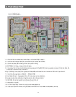
5-1-3) W/E/S Option
1. It controls the Coolselect Zone Damper and the Damper Heater.
2. It controls the Fridge Damper and the Damper Heater (OPTION).
3. It is the Diode Option setting circuit for option setting.
4. EEPROM : It stores various kinds of data.
5. It is a relay for AC load controlling and operates with the MICOM driving signals received from the Sink IC,
and there is the AC load connector.
6. By receiving various sensor signals, the MICOM eliminates noise and detects the door open/close.
7. It controls the operation of MAIN
→
PANEL PCB.
8. Fan Motor Driver : It supplies 8V~12V to various motors (Option).
8. Buzzer Alarm Circuit (Button Input Sound & Door Open Alarm)
10. MICOM, Clock Generation &Software Reset Circuit.
11. Main Micom (CPU)
12. It is the LED Lamp Control Circuit (F/R LAMP)/(Option).
13. It receives the AC Power and generates DC12V/5V for the MAIN PCB (SMPS Circuit).
Содержание RL60GG Series
Страница 12: ...12 2 PRODUCT SPECIFICATIONS 592 1201 7 595 500 584 675 712 2010 2 4 Dimensions mm RL60 RL58 RL56 2010 1920 1850...
Страница 75: ...75 5 PCB DIAGRAM 5 3 Connector Layout and Description Main Board 5 3 1 Q G J OPTION...
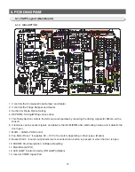
Страница 76: ...76 5 PCB DIAGRAM 5 3 2 R P Z H Option...
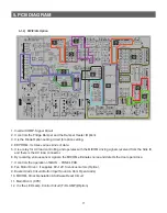
Страница 77: ...77 5 PCB DIAGRAM 5 3 3 L Option...
Страница 78: ...78 5 PCB DIAGRAM 5 3 4 W E Option...
Страница 80: ...80 5 PCB DIAGRAM IPM DIODE VOLTAGE 5 5 IPM Diode Voltage...
Страница 81: ...81 6 WIRING DIAGRAM 6 1 Q G J OPTION...
Страница 82: ...82 6 WIRING DIAGRAM 6 2 R P Z H Option...
Страница 83: ...83 6 WIRING DIAGRAM 6 3 L Option...
Страница 84: ...84 6 WIRING DIAGRAM 6 4 W E Option...
Страница 85: ...85 6 WIRING DIAGRAM 6 5 S Option...
Страница 86: ...86 7 CIRCUIT DIAGRAM 7 1 Schematic Diagram PBA Main 7 1 1 Q G J OPTION...
Страница 87: ...87 7 CIRCUIT DIAGRAM 7 1 2 R P Z H L Option...
Страница 88: ...88 7 CIRCUIT DIAGRAM 7 1 3 W E S Option...
Страница 89: ...89 7 CIRCUIT DIAGRAM 7 2 Schematic Diagram PBA Inverter...
Страница 90: ...90 7 CIRCUIT DIAGRAM 7 3 Block Diagram PBA Main...
Страница 91: ...91 7 CIRCUIT DIAGRAM 7 4 Block Diagram PBA Inverter G H L P R Z Option...
Страница 92: ...92 7 CIRCUIT DIAGRAM 7 5 Block Diagram PBA Inverter Q J Option...
Страница 93: ...93 8 REFERENCE INFORMATION 9 2 Nomenclatrue...


