32
4. TROUBLESHOOTING
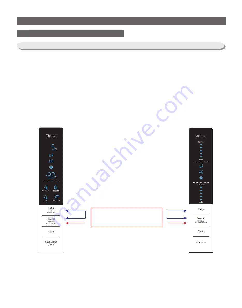
1. When the Freezer and the Fridge buttons on the display panel are held down for more than 6
seconds, the Panel Display will blink at an interval of 0.5 second for 4 seconds.
At this time, release both of the Freezer and the Fridge buttons and press the Freezer button to
enter the Test Mode.
2. When entering the Test Mode, it works as the Test button whatever button on the display panel is
pressed.
3. Each time the Test button is pressed, it will change in the following order.
Forced Operation
→
Forced F-Defrost
→
Cancellation (Normal Operation)
→
Forced Operation.
4. It is recommended that the unit be re-plugged in to terminate the operation of the Test function.
1) Test Mode Entering Process
4-1) Check-List before Trouble-Shooting
4-1-1) Test Function (Forced Operation / Forced Defrost)
①
HOLD 6 SEC.
②
Press "Freezer" Button
①
Press for 6 seconds at the same time.
②
When pressing the Freezer button, it will go into the Test Mode.
BAR-TYPE
7-Segment
Содержание RL60GG Series
Страница 12: ...12 2 PRODUCT SPECIFICATIONS 592 1201 7 595 500 584 675 712 2010 2 4 Dimensions mm RL60 RL58 RL56 2010 1920 1850...
Страница 75: ...75 5 PCB DIAGRAM 5 3 Connector Layout and Description Main Board 5 3 1 Q G J OPTION...
Страница 76: ...76 5 PCB DIAGRAM 5 3 2 R P Z H Option...
Страница 77: ...77 5 PCB DIAGRAM 5 3 3 L Option...
Страница 78: ...78 5 PCB DIAGRAM 5 3 4 W E Option...
Страница 80: ...80 5 PCB DIAGRAM IPM DIODE VOLTAGE 5 5 IPM Diode Voltage...
Страница 81: ...81 6 WIRING DIAGRAM 6 1 Q G J OPTION...
Страница 82: ...82 6 WIRING DIAGRAM 6 2 R P Z H Option...
Страница 83: ...83 6 WIRING DIAGRAM 6 3 L Option...
Страница 84: ...84 6 WIRING DIAGRAM 6 4 W E Option...
Страница 85: ...85 6 WIRING DIAGRAM 6 5 S Option...
Страница 86: ...86 7 CIRCUIT DIAGRAM 7 1 Schematic Diagram PBA Main 7 1 1 Q G J OPTION...
Страница 87: ...87 7 CIRCUIT DIAGRAM 7 1 2 R P Z H L Option...
Страница 88: ...88 7 CIRCUIT DIAGRAM 7 1 3 W E S Option...
Страница 89: ...89 7 CIRCUIT DIAGRAM 7 2 Schematic Diagram PBA Inverter...
Страница 90: ...90 7 CIRCUIT DIAGRAM 7 3 Block Diagram PBA Main...
Страница 91: ...91 7 CIRCUIT DIAGRAM 7 4 Block Diagram PBA Inverter G H L P R Z Option...
Страница 92: ...92 7 CIRCUIT DIAGRAM 7 5 Block Diagram PBA Inverter Q J Option...
Страница 93: ...93 8 REFERENCE INFORMATION 9 2 Nomenclatrue...

