25
3. DISASSEMBLY & REASSEMBLY
Warning
Read these instructions completely and carefully
1. Handle parts carefully to avoid scratching paint.
2. Set screws down by their related parts to avoid using them in the wrong places.
3. Provide a non-scratching work surface for the doors.(ex:blanket)
4. During door reversing,refrigerator should not be stained with oil.
• Before reversing the door,first of all,main power should be switched off.you should take out contents and
accessories like door guard from the doors.Be careful not to drop the doors during dissembling or assembling.
3-7) Reversing the Door swing
PART NAME
FIGURE
DESCRIPTION
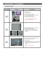
Disassembly
of the
refrigerator
door
1. Afer removing screws, disassemble the
COVER HINGE B
2. Disconnect electric wires inside of the
COVER HINGE B
When diassembling, make sure
the unit turned off.
3. With a 10mm socket wrench, remove bolts on
the top of the refrigeator.
4. Disassemble the Fridge door by lifting it
upward. Be careful not to drop and scratch the
face of the Fridge door.
Be careful not to scratch.
NOT PROVIDED
ADDITIONAL
PART
Phillips Head
Driver (+)
Flat Head
Driver (-)
10mm Socket
Wrench (for bolts)
11mm Wrench
(for hinge shaft)
3/16” Allen
Wrench
(for middle hinge)
Top Left Hinge
Cover (Underneath
the Top Cover)
Содержание RL60GG Series
Страница 12: ...12 2 PRODUCT SPECIFICATIONS 592 1201 7 595 500 584 675 712 2010 2 4 Dimensions mm RL60 RL58 RL56 2010 1920 1850...
Страница 75: ...75 5 PCB DIAGRAM 5 3 Connector Layout and Description Main Board 5 3 1 Q G J OPTION...
Страница 76: ...76 5 PCB DIAGRAM 5 3 2 R P Z H Option...
Страница 77: ...77 5 PCB DIAGRAM 5 3 3 L Option...
Страница 78: ...78 5 PCB DIAGRAM 5 3 4 W E Option...
Страница 80: ...80 5 PCB DIAGRAM IPM DIODE VOLTAGE 5 5 IPM Diode Voltage...
Страница 81: ...81 6 WIRING DIAGRAM 6 1 Q G J OPTION...
Страница 82: ...82 6 WIRING DIAGRAM 6 2 R P Z H Option...
Страница 83: ...83 6 WIRING DIAGRAM 6 3 L Option...
Страница 84: ...84 6 WIRING DIAGRAM 6 4 W E Option...
Страница 85: ...85 6 WIRING DIAGRAM 6 5 S Option...
Страница 86: ...86 7 CIRCUIT DIAGRAM 7 1 Schematic Diagram PBA Main 7 1 1 Q G J OPTION...
Страница 87: ...87 7 CIRCUIT DIAGRAM 7 1 2 R P Z H L Option...
Страница 88: ...88 7 CIRCUIT DIAGRAM 7 1 3 W E S Option...
Страница 89: ...89 7 CIRCUIT DIAGRAM 7 2 Schematic Diagram PBA Inverter...
Страница 90: ...90 7 CIRCUIT DIAGRAM 7 3 Block Diagram PBA Main...
Страница 91: ...91 7 CIRCUIT DIAGRAM 7 4 Block Diagram PBA Inverter G H L P R Z Option...
Страница 92: ...92 7 CIRCUIT DIAGRAM 7 5 Block Diagram PBA Inverter Q J Option...
Страница 93: ...93 8 REFERENCE INFORMATION 9 2 Nomenclatrue...


