24
3. DISASSEMBLY & REASSEMBLY
3-6) Machine Compartments
PART NAME
FIGURE
DESCRIPTION
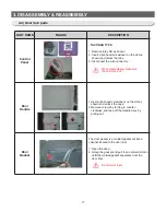
The electric box is located at the top of the
refrigerator.
1. Remove 2 screws at the indicated parts on the
figure.
2. Lift up the back side of the cover and pull out
on your side.
When disassembling, make sure
the refrigerator turned off.
PART NAME
FIGURE
DESCRIPTION
Evaporator
In Freezer
Accumulator
Thermistor
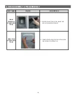
Evaporator is located in the bottom of freezer to
produce cold air driven across the evaporator
Coils.
1. Take off the ductwork in Freezer.
2. Disconnect the wire connector
(Heater,Bimetal,and Thermistor).
3. Cut the pipes, desoldering is dangerous with
R600a charged appliances.
4. Remove the evaporator.
5. Take the same steps to seal the system as
mentioned earlier.
Freezer
Thermistor
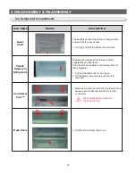
The freezer thermistor is located at the upper left
of freezer vent.
It sends temperature signals to the micro-
processor.
Содержание RL60GG Series
Страница 12: ...12 2 PRODUCT SPECIFICATIONS 592 1201 7 595 500 584 675 712 2010 2 4 Dimensions mm RL60 RL58 RL56 2010 1920 1850...
Страница 75: ...75 5 PCB DIAGRAM 5 3 Connector Layout and Description Main Board 5 3 1 Q G J OPTION...
Страница 76: ...76 5 PCB DIAGRAM 5 3 2 R P Z H Option...
Страница 77: ...77 5 PCB DIAGRAM 5 3 3 L Option...
Страница 78: ...78 5 PCB DIAGRAM 5 3 4 W E Option...
Страница 80: ...80 5 PCB DIAGRAM IPM DIODE VOLTAGE 5 5 IPM Diode Voltage...
Страница 81: ...81 6 WIRING DIAGRAM 6 1 Q G J OPTION...
Страница 82: ...82 6 WIRING DIAGRAM 6 2 R P Z H Option...
Страница 83: ...83 6 WIRING DIAGRAM 6 3 L Option...
Страница 84: ...84 6 WIRING DIAGRAM 6 4 W E Option...
Страница 85: ...85 6 WIRING DIAGRAM 6 5 S Option...
Страница 86: ...86 7 CIRCUIT DIAGRAM 7 1 Schematic Diagram PBA Main 7 1 1 Q G J OPTION...
Страница 87: ...87 7 CIRCUIT DIAGRAM 7 1 2 R P Z H L Option...
Страница 88: ...88 7 CIRCUIT DIAGRAM 7 1 3 W E S Option...
Страница 89: ...89 7 CIRCUIT DIAGRAM 7 2 Schematic Diagram PBA Inverter...
Страница 90: ...90 7 CIRCUIT DIAGRAM 7 3 Block Diagram PBA Main...
Страница 91: ...91 7 CIRCUIT DIAGRAM 7 4 Block Diagram PBA Inverter G H L P R Z Option...
Страница 92: ...92 7 CIRCUIT DIAGRAM 7 5 Block Diagram PBA Inverter Q J Option...
Страница 93: ...93 8 REFERENCE INFORMATION 9 2 Nomenclatrue...


