


EB 8091-1 EN
17
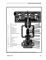
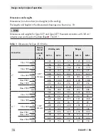
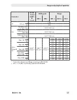
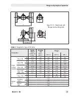
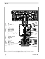
Design and principle of operation
Connection
Female
thread
Welding ends
Flanges
G/NPT/
Rc
1
/
8
to ¾
NPS ½
NPS 1
NPS ½
NPS ¾
NPS 1
H1
120 cm²
in
4.80
mm
122
H4
Insulating section
up to Class 2500
10.35”/263 mm
Bellows seal up to
Class 600
10.35”/263 mm
Bellows seal up to
Class 1500
14.37”/365 mm
H2 or
flange Ø
D1
Class 150
in
0.90”
2)
23 mm
2)
0.90”
2)
23 mm
2)
0.90”
2)
23 mm
2)
3.54
3.94
4.33
mm
90
100
110
Class 300
in
3.74
4.53
4.91
mm
95
115
125
Class 600
in
3.74
4.53
4.91
mm
95
115
125
Class 900/
Class 1500
in
4.72
5.12
5.91
mm
120
130
150
Class 2500
in
5.31
5.51
6.30
mm
135
140
160
1)
Face-to-face dimensions of flanges according to DIN EN 558
2)
H2 = 1.10” (28 mm) with body material B 574 N06455
Содержание 3510
Страница 29: ...EB 8091 1 EN 29...


