


Electrical Connection
38
ESS Inverter User Manual
c
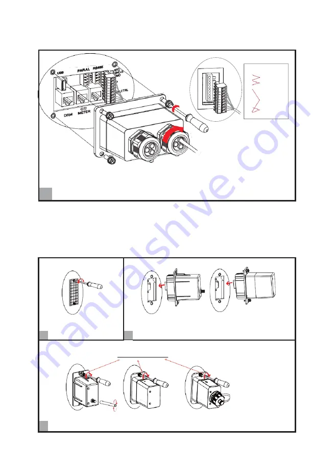
Pin
Function
9
NTC
8
RMO
7
6
5
4
DRY
3
2
GEN_CTRL
1
Insert its 9-Pin terminal into the corresponding NTC/RMO/DRY port on the ESS inverter.
Install the seal into the threaded sleeve, fasten the rubber nut and screw the waterproof cover back
c
to inverter firmly with 4 x M4 screws; 1.2N·m.
4.6.7
GPRS/WIFI/LAN Module Connection (Optional)
For details, please refer to the corresponding Module Installation Guide in the packing.
The appearance of modules may be slightly different. The figure shown here is only for illustration.
Loosen two screws
and move the cover.
Insert GPRS/WIFI/LAN module into GPRS/WIFI/LAN port
,
a
b
and ensure that it does not fall off.
2 x M4 screws; 0.8N.m
Or
Or
0.2~0.3N.m
c
Install the module.