


Electrical Connection
ESS Inverter User Manual
19
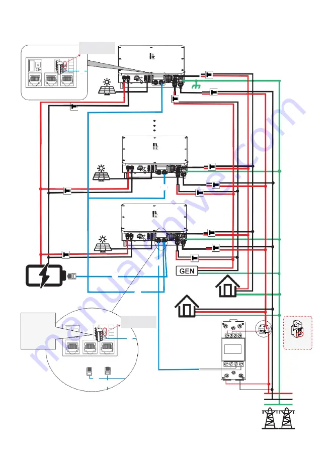
Single phase parallel connection mode-Scheme B (N>5)
USB
PARAL RS485
DRM
①
CT/
METER BMS
PV Array
No.N Inverter
PE
①
No.2 Inverter
PV Array
①
No.1 Inverter
PV Array
Lithium battery/
lead-acid battery
②
③
Smart Load/
Generator
/
①
On-Grid Inverter
Critical Load
Pin Function
USB
PARAL RS485
Normal Load
G GND_S
S PARA_SYNC
L CAN_L
H CAN_H
DRM
①
CT/
METER BMS
②
③
DDSU666
1.5(6)A
9 10
24 25
Flow from grid
to inverter
①
Parallel communication connection
②
CT/Meter communication connection
③
BMS communication connection
* These communication cables can be connected
to any inverter, but they must be inserted into the
same inverter and we call this inverter
No. 1 inverter
.
L
N
PE
Grid
Turn this switch
to “ON”.
Turn this switch
to “ON”.
G
S
L
H
G
S
L
H