


Electrical Connection
ESS Inverter User Manual
33
c
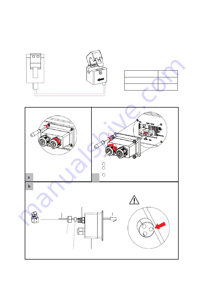
Inverter
CT
Pin5(CT-)
Black
Pin6(CT+)
Red
Pin
5,6
CT-
Lead the CT cable through the rubber nut, seal and waterproof cover in turn.
Threaded
sleeve
Don’t cut off any
communication cables.
CT cable
RJ45
terminals
CT
Inverter
side
Rubber nut
Seal
Waterproof cover
Press the CT cable in the seal
via the side incisions.
Make the RJ45 terminal according to above function description of each Pin definition.
3
Install the seal into the threaded sleeve, fasten the
rubber nut.
c
waterproof cover.
1
Insert RJ45 terminal into corresponding port.
2
Screw the waterproof cover back to inverter firmly
with 4 x M4 screws(1.2N·m).
3
2
1
Unscrew the waterproof cover
and loosen the rubber nut on
4.6.3.2
CT Connection
This section is applicable to non-parallel connection mode and parallel connection-scheme A
only.
CT cable connection overview
CT+
Connect CT. Refer to the following steps: