


Electrical Connection
ESS Inverter User Manual
35
4.6.5
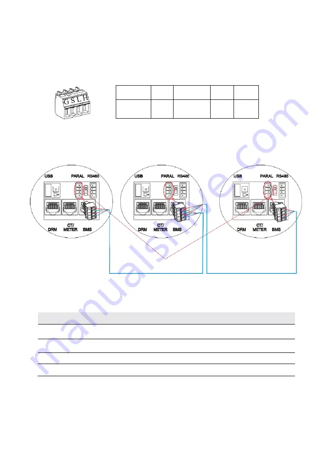
Parallel Communication Connection
4-Pin Terminal Configuration of parallel Communication
PIN
G
S
L
H
Function
Description
GND_S
PARA_SYNC
CAN_L
CAN_H
Parallel communication cable connection overview
No.
1
Inverter
No.
2
Inverter
No.
N
Inverter
It is necessary to turn the matched resistance switch of No.
1
inverter and No.
N
inverter to “ON” in
parallel connection mode.
No. 1 Inverter
No.
2
Inverter
……
No.
N
Inverter
PinH(CAN_H)
PinH(CAN_H)
PinH(CAN_H)
PinL(CAN_L)
PinL(CAN_L)
PinL(CAN_L)
PinS(PARA_SYNC)
PinS(PARA_SYNC)
PinS(PARA_SYNC)
PinG(GND_S)
PinG(GND_S)
PinG(GND_S)
...
Turn the switch to “ON”.