


Electrical Connection
ESS Inverter User Manual
37
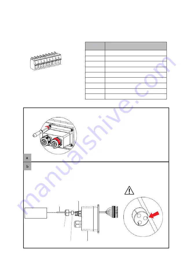
Make the 9-Pin terminal according to above function description of each Pin definition for the
auxiliary port you want to use.
Lead the
NTC/RMO/DRY cable(s)
through the rubber nut, seal and waterproof cover in turn.
Don’t cut off any
communication cables.
NTC/RMO/
DRY cable(s)
Threaded
sleeve
9-Pin
terminal
NTC/RMO/DRY
Control Module(s)
Rubber nut
Inverter
side
Seal
Waterproof cover
Press the NTC/RMO/DRY cable(s)
in the seal via the side incisions.
Unscrew the waterproof cover
and loosen the rubber nut on
waterproof cover.
4.6.6
NTC/RMO/DRY Connection(s)
9-Pin Terminal Configuration of Auxiliary Communication
Pin123456789
Refer to the following steps:
PIN
Function Description
1
NO1 (Generator Control)
2
N1 (Generator Control)
3
NC1 (Normal Close)
4
NO2 (Normal Open)
5
N2 (Common Pole)
6
NC2 (Normal Close)
7
Remote OFF
8
GND_S
9
NTC BAT+