24
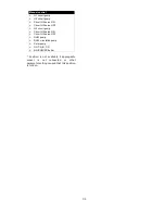
Hydraulic scheme no. 6 - diagram with pelet boiler
6
:
1
–
boiler
2
–
solar collector temperature sensor
3
–
temperature sensor for direct circuit
4
–
DHW tank lower temperature sensor (lower solar
sensor)
5
–
direct heating circuit pump (H1)
6
–
adjustable heating circuit pump (H2)
7
–
valve electrical servo of adjustable circuit (H2)
8
–
water temperature sensor of adjustable circuit (H2)
9
–
valve electrical servo of adjustable circuit (H3)
10
–
adjustable heating circuit pump (H3)
11
–
water temperature sensor of adjustable circuit (H3)
12
–
controller
13
–
weather sensor
14
–
DHW pump
15
–
DHW tank water temperature sensor
16
–
DHW circulating pump
17
–
solar pump
18
–
solar panel
20
–
mechanical protective thermostat for protecting floor
circuit against excessive water temperature
.
PROPOSED SETTINGS:
Parameter
Setting
MENU
Hydraulic diagram
6
menu
→
service setting
→
System
Pump start temperature
55
C
menu
→
service setting
→
System
Minimum temperature
60
C
menu
→
service setting
→
System
→
Main heat source
Hysteresis
5
C
menu
→
service setting
→
System
→
Main heat source
Selection
ON
menu
→
service setting
→
System
→
Main heat source
6
Shown hydraulic diagram does not replace a central heating system and can be used only for demonstrative purposes
!
Содержание Multi-Mix
Страница 7: ...7 USER SETTINGS Multi Mix ...
Страница 13: ...INSTALLATION AND SERVICE SETTINGS Multi Mix ...
Страница 39: ...39 ...
Страница 40: ...40 SALUS Controls ul Rolna 4 43 262 Kobielice www salus controls pl ...


