


20
Hydraulic scheme no. 2 - connection of a fireplace with a water jacket
2
.
Variant A
–
boiler with integrated pump, variant B
–
boiler without an integrated pump.
1
–
boiler
2
–
electrical switching servo with return spring
3
–
coupling temperature sensor
4
–
hydraulic coupling
5
–
boiler pump
6
–
temperature sensor of water inside the boiler with
water jacket
7
–
fireplace with a water jacket
8
–
water pump of the fireplace with water jacket
9
–
thermostatic valve protecting return temperature.
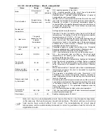
PROPOSED SETTINGS:
Parameter
Setting
MENU
V
ar
ia
n
t
A
Hydraulic diagram
2
menu
→
service settings
→
System
Selection
ON
menu
→
service settings
→
System
→
Additional heat source
Temp. deactivation of main heat
source
35
C
menu
→
service settings
→
System
→
Additional heat source
Pump start temperature (8)
55
C
menu
→
service settings
→
System
→
Additional heat source
Cooling temperature
92
C
menu
→
service settings
→
System
→
Additional heat source
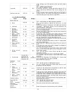
V
ar
ia
n
t
B
Selection
ON
menu
→
service settings
→
System
→
Additional heat source
Hydraulic diagram
2
menu
→
service settings
→
System
Temp. deactivation of main heat
source
35
C
menu
→
service settings
→
System
→
Additional heat source
Pump start temperature (8)
55
C
menu
→
service settings
→
System
→
Additional heat source
Minimum temperature
50
C
menu
→
service settings
→
System
→
Additional heat source
Cooling temperature
92
C
menu
→
service settings
→
System
→
Additional heat source
D
esc
ri
p
ti
o
n
Variant A
: After heating the fireplace sensor (6) up to a temperature (35
C) the boiler (1) is disabled along with an
integrated pump. After heating the sensor (6) up to a temperature (55
C), valve (2) is switched and fireplace pump
(8) is enabled. When sensor (6) exceeds 92
C, heat excess will be transferred to heat and HUW circuits.
Variant B
: When a fireplace sensor (6) is heated up to a temperature of (35
C), the boiler (1) turns off. After heating
sensor (6) up to a temperature of (55
C), valve (2) switches over, pump (5) switches off and fireplace pump (8)
switches on. When sensor (6) exceeds 92
C, heat excess will be transferred to heat and HUW circuits. When fireplace
(7) is cold, pump (5) switches off and on in accordance with indications of temperature sensor (3) and Minimum
temperature parameter settings
.
2
Shown hydraulic diagram does not replace a central heating system and can be used only for demonstrative purposes
!
Содержание Multi-Mix
Страница 7: ...7 USER SETTINGS Multi Mix ...
Страница 13: ...INSTALLATION AND SERVICE SETTINGS Multi Mix ...
Страница 39: ...39 ...
Страница 40: ...40 SALUS Controls ul Rolna 4 43 262 Kobielice www salus controls pl ...