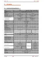
background image

41

SALICRU

Models:

TWIN PRO

TWIN/3 PRO 

 10 kVA

TWIN/3 PRO > 10 kVA

Available powers (kVA / kW)

4 / 3.6

5 / 4.5

6 / 5.4

8 / 7.2

10 / 9

8 / 7.2

10 / 9

12 / 10.8  15 / 13.5

20 / 18

Batteries

Voltage / capacity

12 V DC / 7 Ah

12 V DC / 9 Ah

12 V DC / 9 Ah

Quantity of batteries in serial / set voltage

20 / 240 V DC

24 / 288 V DC

Quantity batteries set

1

2

Low battery voltage, block / set

11.4 V DC / 228 V DC

11.4 V DC / 273.6 V DC

End battery voltage:
- From 0-30 % load, block / set

10.7 V DC / 214 V DC

10.7 V DC / 256.8 V DC

- From 30-70 % load, block / set

10.2 V DC / 204 V DC

10.2 V DC / 244.8 V DC

- From > 70 % load, block / set

9.5 V DC / 190 V DC

9.5 V DC / 228 V DC

Internal battery charger

Type of charge

I / U (Constant current / constant voltage)

Constant current / constant voltage

1 or 1.4 A depending on model / 273 V DC

(13.65 V DC block)

4 A / 345.6 V DC

(14.4 V DC block.)

Floating voltage, block / set

13.65 V DC / 273 V DC

13.65 V DC / 327.6 V DC

Maximum charging current

1 A

1.4 A

4 A

Recharging time

5 hours at 90%

Leakage current

< 500 µA

Voltage / temperature compensation

– 3 mV / ºC per battery annd above 25 ºC

Internal battery charger option (B1)

Maximum charging current

4 A

8 A

Generals

Communication ports

2 (RS232 -DB9- and USB, mutally exclusive)

Monitoring software

WinPower (free download)

Noise level at 1 m.

< 50 dB

< 55 dB

Operating temperature

0.. 45 ºC

Storage temperature

– 15.. + 50 ºC

Storage temperature without batteries

– 20.. + 70 ºC

Operating altitude

< 1000 m (for higher altitudes correct according to table 14)

Relative humidity

0-95 % non-condensing

Protection degree

IP20

Dimensions -Depth x Width x Height- (mm)

550 x 260 x 708

650 x 350 x 890

Weight (kg) -Standard UPS-

72

73

74

85

86

87

88

189

190

191

Weight (kg) -B0 version UPS-

14

15

16

26

27

28

29

58

59

60

Weight (kg) -B1 version UPS-

16

17

18

29

30

31

32

63

64

65

Safety

EN-IEC 62040-1; EN-IEC 60950-1

Electromagnetic compatibility (EMC)

EN-IEC 62040-2

Marking

CE

Quality system

ISO 9001 and ISO 140001

Table 13. 

General technical specifications.

Altitude (m.) 1000 1500 2000 2500 3000 3500 4000 4500 5000
Power

100% 95%

91%

86% 82%

78%

74%

70%

67%

Table 14. 

Power correction in relation to the working height.

8.2.  Glossary.

• 

AC.-

 It is nominated as alternating current (abbreviation 

in Spanish CA and in English AC) to the electrical current 

in which the magnitude and direction varies in a cyclic 

way. The most common wave shape of the alternating 

current is sinewave, because the energy transmission 

is better. Nevertheless, some applications could need 

other period wave shapes, like triangular or square 

• 

Bypass.-

 Manual or automatic, it is the physical junction be-

tween the input and the output electric device.

• 

DC.-

 The direct current (CC in Spanish, DC in English) is the 

continuous electron flow through a cable between two points 

with different potential. Unlike the alternating current, in direct 

current the electrical loads always flow in the same direction 

from the highest potential point to the lowest one. Although, 

usually the direct current is identified with the constant cur-

rent (for example the one supplied by the battery), it is con-

tinuous any current that always maintain the polarity.

• 

DSP.-

 It is the acronym of Digital Signal Processor. A DSP is 

a system based on a processor or microprocessor that has 

instructions in it, a hardware and an optimised software to 

develop applications where numerical operations are needed 

with very fast speed. Due to this, it is very useful to process 

analogical signals in real time: in a system that runs in this 

way (real time) samples are received, usually coming from an 
analogical/digital converter(ADC).

• 

Power factor.-

 It is defined as power factor, p.f., of an alter-

nating current circuit, as the ratio between the active power, 

P, and the apparent power, S, or as the cosines of the angle 

that make the current and voltage vectors, designating as 

cos φ, being φ the value of that angle.

• 

GND.-

 The term ground, as its name states, refers to the po-

tential of the earth surface.

• 

EMI filter.-

 Filter able to decrease the electromagnetic inter-

ferences, which is the perturbation that happens in a radio 

receptor or in any other electrical circuit caused by the elec-

tromagnetic radiation coming from an external source. Also 

it is known as EMI, ElectroMagnetic Interference, Radio Fre-

quency Interference or RFI. This perturbation can derate or 

limit the efficiency of the circuit.

Содержание SLC TWIN PRO Series

Страница 1: ...PS LIGHTING FLOW DIMMER STABILIZERS ILUEST SWITCH MODE POWER SUPPLY STATIC INVERTERS PHOTOVOLTAIC INVERTERS VOLTAGE STABILIZERS AND POWER LINE CONDITIONERS UPSSLCTWINPROseries 4 to 20 kVA UNINTERRUPTI...

Страница 2: ......

Страница 3: ...ing 5 1 Commissioning 5 1 1 Controls before commissioning 5 2 Start up and shutdown of the UPS 5 2 1 Start up of the UPS with mains present 5 2 2 Start up of the UPS without mains 5 2 3 UPS shutdown w...

Страница 4: ...structions for safety of the things To not respect such instructions can damage the goods Precaution symbol Read the paragraph text and take the stated preventive mediums it contents the basic instru...

Страница 5: ...chnical Regulations or standards of the country Use approved cables only Protection Earth cable of the UPS drives the leakage current of the load devices An isolated earth cable has to be installed as...

Страница 6: ...r cause can make an electrical discharge of high voltage and it is restricted to qualified staff only Do not open the equipment A part from the implicit stated risks any action that make the modificat...

Страница 7: ...hem Do not modify its length In those equipments requested without batteries their ac quisition installation and connection of themselves will be done by the end user and under his responsibility Data...

Страница 8: ...ive EMC In accordance with the specifications of the harmonized stand ards Standards as reference EN IEC 62040 1 Uninterruptible power supply UPS Part 1 1 General and safety requirements for UPS s use...

Страница 9: ...due to the constant evolution of the product some discrepancies or small contradictions can arise In front of any doubt the labelling of the equipment will always prevail i Figures regarding its main...

Страница 10: ...USB Protection cover for external batteries IEC output connectors Protection cover for manual bypass switch maintenance and output Protection cover for power blocks USB RS 232 EPO Protection cover for...

Страница 11: ...11 SALICRU Battery switch Protection cover for power blocks Batteries module for models 10 kVA Batteries module for models up to 10 kVA Battery switch Power blocks Fig 3 Rear view batteries module...

Страница 12: ...ews and electrical cables Batteries owned by the client will be installed out from the case or cabinet of the UPS Under request it is possible to supply the acces sories screws and electrical cables n...

Страница 13: ...user s installation wiring is achieved as well as low input current distortion so mains pollution is decreased Great adaptability to the worst conditions of the input mains Wide margins of the input v...

Страница 14: ...tor The big IT systems based on LANs and WANs that integrate servers with different platforms they have to include an easy way of controlling and management at the manager system dis posal This facili...

Страница 15: ...es type B for RCD devices and C characteristic for circuit breakers For the output load feeding C characteristic for circuit breaker Regarding the size they will be as minimum to the cur rents stated...

Страница 16: ...any start it up according to the instructions described in this manual and charge them for 2 hours from floating level In parallel systems it is not needed to make the connection among the equipments...

Страница 17: ...all ends of the cables connected to the power blocks input output and by pass Check the correct torque in the screws of the power blocks In installations with only one UPS the Jumper cable as bridge...

Страница 18: ...is done through the terminals of the own UPS MC coil out and MC coil in R N R S T N R N U N 1 3 2 SAI Backfeed protection connection in TWIN 3 PRO 10 kVA Backfeed protection signal Backfeed protectio...

Страница 19: ...wn in any of the machines connected to the device causing a short circuit it will affect to no more than the line that is faulty The rest of the connected loads will have their continuity as sured due...

Страница 20: ...of each equipment with its external battery cabinet s has to be done like if they were single units completely separate from the rest ones Each battery module is independent for each equip ment It is...

Страница 21: ...tput static bypass this last one for TWIN 3 PRO 10 kVA models only also a manual bypass with mechanical lock see figures 12 and 13 This switchgear panel allows isolating only one equipment from the sy...

Страница 22: ...oltage circuit of safety To preserve the quality it has to be installed separate from other lines that have dangerous voltages energy distribution line UPS has a dry contact card for the relays interf...

Страница 23: ...imum before using the UPS for first time For models with single phase input TWIN PRO or three phase TWIN 3 PRO up to 10 kVA It will be necessary to supply power supply voltage to the equipment and tur...

Страница 24: ...attery switch is in position On models B0 and B1 Turn the input M1 and bypass M2 circuit breakers to On Switch M2 is only available in models TWIN 3 PRO 10 kVA In equipments with single phase input TW...

Страница 25: ...will transfer to Bypass mode Put all the equipments on manual bypass To do it re move the cover from manual bypass switch which is located at the back of each equipment and turn all the switches to p...

Страница 26: ...he UPSs have to be set contact with the S T S Press over the shutdown key in any UPS for more than 3 seconds and each one will be shutdown supplying output voltage through the bypass Turn On the outpu...

Страница 27: ...ot be fed Turn the manual bypass switch of the panel to Off UPS and put the mechanical lock To avoid wrong manoeuvring the mechanical lock has to be fit otherwise the equipment and loads are exposed t...

Страница 28: ...g Press the key for 1 sec as minimum to validate the modified option and change the settings Table 6 Functionality of the buttons or keypad of the control panel The UPS has a control panel with the fo...

Страница 29: ...TWIN Blue 72 Warning On maintain Bypass UPS only 8 20 kVA TWIN 3 Blue Code Condition Description Color LCD 81 Fault Heatsink over temperature Red 82 Alarm Ambient over temperature UPS only 4 10 kVA TW...

Страница 30: ...ad level connected to the UPS UPS power supply information three phase input UPS output information Equipment Battery information Fig 18 Main screen of the equipment with three phase input All the scr...

Страница 31: ...supply fails due to fault or wrong the equipment will transfer to Battery mode to feed the load s properly Fig 24 Frequency converter mode screen This function can be activated through the settings of...

Страница 32: ...ucture of the main menu includes six submenus UPS status Event log Measurement Control Identification Setting With password only and by the S T S 6 3 2 UPS status submenu When pressing the key for les...

Страница 33: ...ucture of UPS status menu Structure of main menu Press 1 sec Fig 31 UPS status screen Press 1 sec Press o 1 sec Structure of Data logger submenu Structure of main menu Press 1 sec Fig 32 Event logger...

Страница 34: ...rd only Fig 34 Control submenu screens 6 3 5 Control submenu When pressing the key the key for less than 1 sec from this Control submenu it is accessed to the control structure see figure 34 Shutdown...

Страница 35: ...ndard configuration from factory 6 4 1 Operating on ECO mode 6 4 1 1 Short description of the ECO mode ECO mode function allows supplying the load s from mains directly through the internal filters on...

Страница 36: ...en used for long time In hot areas battery has to be charged every 2 months The charging time has to be 12 hours as minimum Under normal conditions the battery lifetime is from 3 to 5 years 25 C In ca...

Страница 37: ...the UPS cooling and the ambient temperature of the room NTC abnormal UPS internal fault Consult with the S T S Communication cable male disconnected Para cable Male Loss Alarm code E3 Parallel bus ca...

Страница 38: ...oltage Inv Under Voltage Alarm code 33 UPS internal fault Consult with the S T S Inverter Softstart Failed Inv Softstart Fail Alarm code E34 UPS internal fault Consult with the S T S Negative Power Fa...

Страница 39: ...7 3 1 Covered product UPS SLC TWIN PRO series 7 3 2 Warranty terms This product is guaranteed against any parts and or labour defect for 12 months period from its commissioning by our company staff o...

Страница 40: ...age THD with non linear load 5 Output voltage recovering time 100 ms IEC 62040 3 70 ms IEC 62040 3 60 ms IEC 62040 3 Transient response of the output voltage with load fluctuation of 0 100 0 9 7 7 Tra...

Страница 41: ...elation to the working height 8 2 Glossary AC It is nominated as alternating current abbreviation in Spanish CA and in English AC to the electrical current in which the magnitude and direction varies...

Страница 42: ...rcuit when it over comes the maximum set values On Line mode Regarding to an equipment it is on line when it is connected to the system and it is in operation and usually has its power supply turned o...

Страница 43: ...43 SALICRU...

Страница 44: ...NCIA VALLADOLID ZARAGOZA BRANCHES AND SERVICES AND TECHNICAL SUPPORT S T S CHINA FRANCIA HUNGR A MARRUECOS M XICO PORTUGAL REINO UNIDO SINGAPUR SUBSIDIARIES ALEMANIA ARABIA SAUD ARGELIA ARGENTINA B LG...

Отзывы: