25
SALICRU
5.3. Operative for a parallel system.
•
The following operative, it is considered for equipments with
the configuration preset from factory.
•
Check that the load/s and output circuit breakers switches
from protection panel, are in position "Off".
•
Turn "On" the following circuit breaker switches:
All the input switches from protection panel.
The input ones of each UPS.
In equipments with static bypass line (
TWIN/3 PRO
> 10
kVA), the bypass ones from protection panel.
In equipments with static bypass line (
TWIN/3 PRO
> 10
kVA), the bypass ones of each UPS.
UPSs supply output voltage through the bypass. Check the
LCD from control panel, in case there was any warning or
error information. Check the output voltage at the power
blocks of each UPS separately, in order to check the voltage
difference is below 1V among them. If the difference is higher
than 1 V, double check the wiring and associated instruc-
tions.
•
Press over the start up key for more than 1 second in any
of the UPSs and all of them will start up. All UPSs will transfer
to "Normal mode”.
Measure the output voltage on each UPS separately, to
check the voltage difference is under 0,5 V. In case the differ-
ence were higher than 1 V, the UPSs have to be set (contact
with the
S.T.S.
).
•
Press over the start up key for more than 3 seconds in any
UPS and all of them will be shutdown, at the output will be
voltage supplied through the bypass.
Turn “On” the output circuit breaker switches from the dis-
tribution panel and the complete parallel system will supply
output voltage through the bypass.
•
Press over the start up key for more than 1 second in any
of the UPSs and all of them will start up., finally the parallel
system will be working on "Normal mode”
•
Start up the load/s.
5.4. How to integrate a new UPS in an
operating parallel system.
•
The descriptions hereby detailed are referred to the inte-
gration of one equipment. For two equipments, the tasks to
make are the same less the quantity of units and connec-
tions. Proceed accordingly.
•
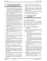
Attend the instructions stated in section 4.3.7.2, for parallel
connection.
•
Protection panel must have the corresponding input, output
and static bypass switches (the last one in
TWIN/3 PRO
> 10
kVA version only), and also the manual bypass.
•
Due to it is needed to modify the own parallel bus con-
nection, in order to integrate the new equipment into the
system (wiring bundle with DB25 connectors), the load
feeding will have to be transferred to manual bypass.
Proceed as follows:
Press over the key in any UPS for more than 3 sec-
onds to shutdown all the inverters. The acoustic alarm
will beep for 3 seconds. The equipments that belong to
the current parallel system will transfer to "Bypass mode".
Put all the equipments on manual bypass. To do it re-
move the cover from manual bypass switch, which is
located at the back of each equipment and turn all the
switches to position "BYPASS".
Keep in mind that on "Bypass mode" or with the
switch on position "BYPASS", the loads will be
exposed to fluctuations of voltage, frequency and mains
faults or blackouts, so in case it were possible choose
one day with the lowest probability of faults (days without
fluctuations, days without storms,... ) and do it as fast as
possible.
Turn the input and bypass circuit breaker protections
(
TWIN/3 PRO
> 10 kVA) of each equipment to "Off".
Turn "Off" the output circuit breaker of the protection
panel, corresponding to the new UPS to be integrated.
Disconnect the communication bus between the first and
last equipment, and reconnect it including the new UPS.
It is essential to close the bus loop to have a good opera-
tion.
•
Turn "On" the following circuit breaker switches:
Each one from the input of each UPS.
In those equipments with static bypass line (
TWIN/3 PRO
> 10 kVA), also the bypass ones of each UPS.
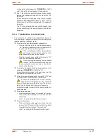
UPSs supply output voltage from bypass. Check the screen
of the LCD from control panel in case there were any warning
or error information.
Measure the output voltage in the power blocks of the parallel
system and in the output terminals of the new UPS, check
the voltage difference is below 1 V. In case the difference
were higher than 1 V, double check the wiring and associated
instructions.
•
Put back the cover of the manual bypass of each UPS.
•
Press over the start up key for more than 1 second in any
of the UPSs and all of them will start up. All UPSs will transfer
to "Normal mode”.
Measure the output voltage between the terminals
JP1
of the
parallel system and terminals
JP1
of the new UPS, to check
the voltage difference is under 0,5 V. In case the difference
were higher than 1 V, the UPSs have to be set (contact with
the
S.T.S.
)
•
Press over the shutdown key in any UPS for more than
3 seconds and each one will be shutdown, supplying output
voltage through the bypass.
Turn “On” the output circuit breaker switch of the distribution
panel, corresponding to the new integrated equipment. The
complete parallel system will supply output voltage, through
the bypass.
•
Remove the cover of the manual bypass in each UPS.
•
Transfer the equipments with the manual bypass ("BYPASS"
position) to position "UPS". Do it in the switches of all equip-
ments.
•
Put back the protection cover of the manual bypass
switch of all equipments, also check the torque of the
fixing screws, otherwise any of the limit contacts could be
activated and the manual bypass too.
•
Press over the start up key for more than 1 second in any
of the UPSs and all of them will start up, finally the parallel
system will be working on "Normal mode”.
Load/s are protected by the parallel system again.
Содержание SLC TWIN PRO Series
Страница 2: ......
Страница 43: ...43 SALICRU...


