


19
SALICRU
•
Connect the power supply cables to bypass power blocks
R (M2)
and
N
,
by respecting the rotation of phase and
neutral
stated in the labelling of the equipment and in this
manual (see figure 11). If this phase, neutral rotation is not
respected there will be serious fault/s in the equipment.
When discrepancies exist between the labelling and the in-
structions of this manual, the labelling will always prevail.
•
In parallel systems, the length and cross section of the
cables that go from the switchgear panel till one of the
UPSs and vice versa, will be the same for all of them without
any exception.
•
In equipments with separate bypass line, a galvanic
isolation transformer has to be installed in any of the
two lines that supply the UPS (rectifier input or static bypass),
to avoid the direct union of the neutral of both lines through
the internal wiring of the equipment .
This is applicable when the two lines are supplied from dif-
ferent mains, i.e.:
Two different electrical companies.
An electrical company and genset, ...
4.3.3. Connection to output power block.
•
As this is a device with class I protection against elec-
tric shocks, it is essential to install a protective earth
conductor (connect earth(
)
). Connect the conductor to
the terminal, before connecting the power supply to the input
power block.
•
Connect the loads to output power block
U (L)
and
N
,
by
respecting the phase and neutral rotation
stated in the
labelling of the equipment and this manual (see figure 11).
When discrepancies exist between the labelling and the in-
structions of this manual, the labelling will always prevail.
•
In parallel systems, the length and cross section of the
cables that go from the switchgear panel till one of the
UPSs and vice versa, will be the same for all of them without
any exception.
•
With respect to the protection that must be placed at the
output of the UPS, we recommend that the output power
should be distributed in at least four lines. Each one should
have a circuit breaker protection switch of a value of one
quarter of the nominal power. This type of power distribu-
tion will allow that in the event of a breakdown in any of the
machines connected to the device causing a short-circuit, it
will affect to no more than the line that is faulty.
The rest of the connected loads will have their continuity as-
sured due to the triggering of the protection, because the
line affected by the short-circuit will trip its protection.
In
pu
t e
ar
th b
on
di
ng
In
pu
t n
eu
tra
l N
In
pu
t p
ha
se R (
L)
B
at
te
ry t
er
m
in
al (
+)
B
at
te
ry
te
rm
in
al
(–)
B
at
te
ry e
ar
th b
on
di
ng
P
ar
al
le
l c
onne
ct
io
n JP
1
P
ar
al
le
l c
onne
ct
io
n JP2
O
ut
put
n
eut
ra
l N
O
ut
pu
t p
ha
se U (
L)
O
ut
pu
t e
ar
th b
on
di
ng
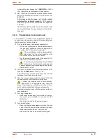
UPS connection power block (TWIN PRO).
In
pu
t p
ha
se R (
L1
)
In
pu
t p
ha
se S (
L2
)
In
pu
t p
ha
se T (
L3
)
In
pu
t n
eu
tra
l N
In
pu
t e
ar
th b
on
di
ng
Fa
se d
e b
yp
as
s R (
M
2)
N
eu
tro d
e b
yp
as
s N
B
yp
as
s e
ar
th b
on
di
n
O
ut
pu
t p
ha
se U (
L)
O
ut
put
n
eut
ra
l N
O
ut
pu
t e
ar
th b
on
di
n
P
ar
al
le
l c
onne
ct
io
n JP
1
P
ar
al
le
l c
onne
ct
io
n JP2
B
at
te
ry t
er
m
in
al (
+)
B
at
te
ry
te
rm
in
al
(–)
B
at
te
ry e
ar
th b
on
di
ng
UPS connection power block (TWIN/3 PRO > 10 kVA).
UPS connection power block (TWIN/3 PRO up to 10 kVA).
In
pu
t e
ar
th b
on
di
ng
In
pu
t p
ha
se R (
L1
)
In
pu
t p
ha
se S (
L2
)
In
pu
t p
ha
se T (
L3
)
In
pu
t n
eu
tra
l N
P
ar
al
le
l c
onne
ct
io
n JP
1
P
ar
al
le
l c
onne
ct
io
n JP2
O
ut
pu
t p
ha
se U (
L)
O
ut
put
n
eut
ra
l N
O
ut
pu
t e
ar
th b
on
di
ng
Fig. 11.
Connection power block.
4.3.4. Connection of external batteries
(extended back up times).
•
As this is a device with class I protection against elec-
tric shocks, it is essential to install a protective earth
conductor (connect earth(
)
). Connect the conductor to
the terminal, before connecting the power supply to the input
power block.
•
To not respect the stated indications in this sec-
tion and the safety instructions 1.2.3 means a
high risk of electrical discharge and even the death.
Model
Batteries
(U
cell
x Nº) =
U
nominal
/ U
floating
Minimum features of two
poles protection switch
Voltage
DC (V)
Current (A)
SLC-4000-TWIN PRO
(12V x 20) =
240V / 275V
440
20
SLC-5000-TWIN PRO
25
SLC-6000-TWIN PRO
32
SLC-8000-TWIN PRO
40
SLC-10000-TWIN PRO
50
SLC-8000-TWIN/3 PRO
40
SLC-10000-TWIN/3 PRO
50
SLC-12000-TWIN/3 PRO
(12 V x 24) =
288V / 330V
440
50
SLC-15000-TWIN/3 PRO
63
SLC-20000-TWIN/3 PRO
100
Table 2.
Features of protection between the equipment and battery
cabinet.
•
All standard UPSs have batteries in the same enclosure of
the equipment , less those ones as B0 and B1. In the first
ones, the battery protection is done by internal fuses and
there is no access to the end-user.
Содержание SLC TWIN PRO Series
Страница 2: ......
Страница 43: ...43 SALICRU...


