


18
Connect the power supply cables to input power blocks
R
(L1)
,
S (L2)
,
T (L3)
and
N
,
by respecting the phase rotation
and neutral
stated in the labelling of the equipment and in
this manual. If this rotation is not respected, the equipment
will not work. A wrong connection between the neutral and
one phase will make serious or very serious faults.
When discrepancies exist between the labelling and the in-
structions of this manual, the labelling will always prevail.
•
In parallel systems, the length and cross section of the
cables that go from the switchgear panel till one of the
UPSs and vice versa, will be the same for all of them without
any exception.
4.3.2. Connection of bypass power block.
TWIN/3 PRO > 10 kVA only.
•
As this is a device with class I protection against elec-
tric shocks, it is essential to install a protective earth
conductor (connect earth(
)
). Connect the conductor to
the terminal, before connecting the power supply to the input
power block.
•
In accordance with safety standard EN-IEC 62040-1, the in-
stallation has to be provided with a «Backfeed protection»
system, as for example a contactor, which will prevent the
appearance of voltage or dangerous energy at the bypass
line during a mains fault (see figure 10 and respect the cir-
cuit diagram of the particular «Backfeed protection» for the
equipment with three phase input (
TWIN/3 PRO
> 10 kVA)).
There can be no derivation in the line that goes from
the «Backfeed protection» to the UPS, as the
standard safety would be infringed.
The control signal of the external contactor for «Backfeed
protection» is done through the terminals of the own UPS
(MC/coil. out and MC/coil. in).
R
N
R
S
T
N
R
N
U
N
(1)
(3)
(2)
SAI
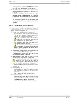
«Backfeed protection» connection in TWIN/3 PRO > 10 kVA.
B
ac
kfe
ed
pr
ot
ec
tion
si
gnal
«Backfeed protection» connection in TWIN PRO.
(3)
(2)
(1)
U
N
UPS
In
pu
t
O
ut
pu
t
O
ut
pu
t
In
pu
t
B
ypa
ss
(1)
Automatic «Backfeed protection» protection system, external to the UPS (EN-IEC 62040-1).
(2)
Fuse holder and fuse for general purpose of 250V AC / 3A type F.
(3)
Two poles contactor of 230V AC with a minimum distance between contact of 1,4 mm and coil of the same voltage, with the minimum current stated
in the nameplate of the UPS (input or bypass according to).
i
For parallel systems, each equipment must have its own "Backfeed protection" completely independent.
MC/
coil. out
MC/
coil. in
R
S
T
N
U
N
(1)
(3)
(2)
SAI
«Backfeed protection» connection in TWIN/3 PRO up to 10 kVA.
O
ut
pu
t
In
pu
t
Fig. 10.
“Backfeed protection” circuit diagram.
Operating:
If bypass thyristor is short-circuited and the UPS is working
on double conversion mode (On-Line), the «Backfeed pro-
tection» contactor will break the bypass line and the mes-
sage «Backfeeder» will be displayed in the LCD panel.
Reset.
To restore the logical control of «Backfeed protection», the
UPS has to be shutdown for a few seconds, and start it again
and acknowledge the alarm in the control panel (see chapter
6).
•
Warning labels should be placed on all primary power
switches installed in places away from the device to alert the
electrical maintenance personnel of the presence of a UPS
in the circuit.
The label will have the following text or an equivalent one:
Before working on this circuit.
•
Isolate Uninterruptible Power System (UPS).
•
Then check for Hazardous Voltage between all
terminals including the protective earth.
Risk of Voltage Backfeed from UPS.
USER MANUAL
Содержание SLC TWIN PRO Series
Страница 2: ......
Страница 43: ...43 SALICRU...


