Hardware Manual for the PCD3 Series│Document 26/789; Version E 5│31.01.2005
Saia-Burgess
Controls Ltd.
Defi nitions of serial interfaces
Appendix
9-4
9
9.2.3
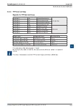
TTY/current loop
Signals to TTY/current loop
Terminal 1
TS
Transmitter Source
Transmitter
Terminal 3
TA
Transmitter Anode
Terminal 6
TC
Transmitter Cathode
Terminal 8
TG
Transmitter Ground
Terminal 2
RS
Receiver Source
Receiver
Terminal 4
RA
Receiver Anode
Terminal 7
RC
Receiver Cathode
Terminal 9
RG
Receiver Ground
Signal type
Required value
Nominal value
Power for logic L (space)
-20 mA to + 2 mA
0 mA
Power for logic H (mark)
+12 mA to +24 mA
+20mA
Neutral voltage to TS, RS
+16 V to +24 V
+24 V
Short circuit power on TS, RS
+18 mA to +29.6 mA
+23.2 mA
The idle state of the data signals = “mark”
By wiring to the cable connector, the user selects either an “active” or “passive”
circuit.
The max. transmission rate for TTY/current loops at 20 mA is 9600 bps.


