Saia-Burgess
Controls Ltd.
Hardware Manual for the PCD3 Series│Document 26/789; Version E 5│31.01.2005
Hardware
PCD3.H100
5-75
5
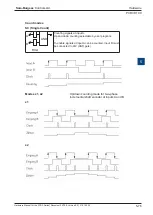
Count modes:
selectable by jumper
Terminal:
Pluggable 10-pole cage clamp terminal (4 405 4957 0)
or pluggable 10-pole screw terminal (4 405 4959 0),
both for wires up to 2.5 mm²
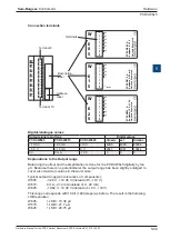
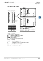
LED’s and connection terminals
Layout (housing opened,
instruction see section 5.1.5
)
Changing the jumpers
Throughout the circuit board there are components which are sensitive to
electrostatic discharges. Explanation will be found in the
Appendix, “Icons” section
.
0
1
2
3
4
5
6
7
LED 0...7 Terminal 0
Description
Label
Address
Label
A
–
B
–
CCO
–
+
–
PCD3.H100
2 Inputs 25 Khz
0
1
2
3
4
5
6
7
8
9
LEDs
En
A
B
CCO
Jumpers
SC
X1
X2
Terminal 9
Terminal
nc
nc
H
1
0
0
LED
In/Output
0
En
1
A
2
B
3
CCO
CCO
B
A
En
SC
x1
x2
Bus connector
Jumper for count modes
LEDs
“A”
input “A”
1
“B”
input “B”
2
“En” (Enable) counter active 0
“CCO”
output “CCO” 3

