background image

Saia-Burgess 

Controls Ltd.

Hardware Manual for the PCD3 Series│Document 26/789; Version E 5│31.01.2005

Hardware

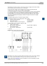
PCD3.A210

5-32

5

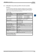
5.3.2  PCD3.A210, 4 relays with “normally closed” contacts, with contact pro- 


tection

Application

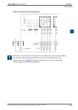
The module contains 4 relays with normally-closed contacts for direct or alternat-

ing current up to 2 A, 250 VAC. The relay contacts are protected by a varistor. The 

module is especially suited wherever perfectly isolated AC switching circuits must be 

controlled with infrequent switching

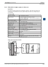
Technical data

Number of outputs per module:  4, electrically isolated NC contacts 

Type of relay (typical):

PE O14 024, SCHRACK

Switching rating: 

(contact lifetime)

2A, 250 VAC AC1 

0,7 x 10⁶ operations 

1 A, 250 VAC AC11 

1,0 x 10⁶ operations 

2 A, 50 VDC DC1 

0,3 x 10⁶ operations 

3

1 A, 24 VDC DC11 

0,1 x 10⁶ operations 

1

3

)

Relay coil supply: 

2

)

nominal 24 VDC smoothed or pulsed,  

9 mA per relay

Voltage tolerance: 

Dependent on 

Ambient temperature

20°C: 17.0...35 VDC 

30°C: 19.5...35 VDC 

40°C: 20.5...32 VDC 

50°C: 21.5...30 VDC

Typical output delay:

5 ms at 24 VDC

Resistance to interference:  

according to IEC 801-4

4 kV under direct coupling 

2 kV under capacitive coupling (whole trunk group)

Internal current consumption: 

(from +5 V bus)

1...15 mA 

typ. 10 mA

Internal current consumption: 

(from V+ bus)

0 mA

External current consumption:

max. 32 mA

Terminal:

Pluggable 10-pole cage clamp terminal (4 405 4957 0) or 

pluggable 10-pole screw terminal (4 405 4959 0), both for 

wires up to 2.5 mm²

1)

 With external protective diode   

2)

 With reverse voltage protection 

3)

 These ratings are not UL-listed!

Содержание PCD3 Series

Страница 1: ...Document No 26 789 Version E5 31 01 2005 Hardware Manual for the PCD3 Series...

Страница 2: ...rsions for the PCD3 Mxxx0 3 8 3 5 Expansion with PCD3 components 3 9 3 6 Mounting CPUs and module holders 3 10 3 6 1 Mounting position and ambient temperature 3 11 3 7 Dimensions 3 11 3 8 Power supply...

Страница 3: ...4 5 3 RS 232 with PCD3 F121 suitable for modem 4 12 4 6 LIOs and RIOs 4 16 5 Input output I O modules 5 1 Introduction to I O modules 5 1 5 1 1 Types of connectors and Accessories 5 3 5 1 2 Power requ...

Страница 4: ...6 Counting and motion control I O modules 5 73 5 6 1 PCD3 H100 Simple counting module 5 74 5 6 2 PCD3 H110 Universal counting and measuring module 5 79 5 6 3 PCD3 H150 SSI interface for absolute enco...

Страница 5: ...marks 26 789 E4 08 01 2005 2005 Translation E5 31 01 2005 31 01 2005 Changes 0 2 Trademarks Saia and Saia PCD are registered trademarks of Saia Burgess Controls AG STEP7 SIMATIC S7 300 S7 400 and Siem...

Страница 6: ...nent connector to jump straight to the corresponding section The facility to jump to any section from the table of contents is still to be completed Plug in serial interfaces in Slot 0 Port 1 4 8 LEDs...

Страница 7: ...e connected to the CPU via the I O bus or a RIO i e with the shortest possible cables Modules Input output elements mounted in a housing matched to the PCD3 system Module holder CPU RIO or LIO to whic...

Страница 8: ...used to extend the I O bus or for the internal power supply 5V and V to a module segment Please note the following rules Use no more than six PCD3 C200s in one con guration or the time delay will exce...

Страница 9: ...d on the sockets with base address 240 Arrange module holders in row s according to the mounting area avaliable Connecting material required Arrangement with one PCD3 Mxx0 LIOs in one row Max 15 x PCD...

Страница 10: ...e CPU RIO PCD3 C200 The max supply current can be found in the section on Internal supply Calculate consumption from the 24V supply The current consumption for the PCD3 con guration can be determined...

Страница 11: ...or exit to the switching cabinet The shields should be as short as possible and of the largest possible cross section The central earthing point should be 10 mm and connected to the PE ground wire by...

Страница 12: ...I Os the entries are de ned by the network con gurator Extension cables connect the module holder at the right hand end of a row with the rst module holder at the left of the next row The address of t...

Страница 13: ...to the power supply 2 4 1 Labelling module holders and modules The sockets for the PCD3 module holders are labelled 0 to 3 Every module holder has an address eld in the bottom right corner of the hous...

Страница 14: ...maintenance by general use of Ethernet TCP IP and Pro bus with S Net the Private Control Network PCN for Saia PCDs General use of web technologies via Ethernet TCP IP and Pro bus for commissioning op...

Страница 15: ...485 modem etc and via Pro bus networks throughout the system and at different levels in the network This makes it economical to use web technology to operate and monitor even the smallest applications...

Страница 16: ...he correct use of these controls in residential areas can be found at www sbc support ch additional measures Noise immunity according to EN 50 082 2 Mechanism and mounting Housing material Module hold...

Страница 17: ...ile range can be con gured beginning with address 0 Registers 32 bit 16384 R 0 16383 For integer or oating point values Text data blocks 8192 X or DB 0 8191 The texts 0 3999 are always written to the...

Страница 18: ...ash 256 kB onboard ash 256 kB onboard ash 1 MByte ash card optional Clock RTC yes deviation 1 min month Data protection 8 hours with Super Cap after 5 min loading CR 2032 lithium battery 1 3 years4 I...

Страница 19: ...erface up to 115 kbps RS 485 serial interface up to 115 kbps Port 2 Pro S Net interface Port 2 up to 187 5 kbps Port 10 up to 1 5 Mbps Ether S Net interface Field bus connections Serial S Net Pro S Ne...

Страница 20: ...event loss of data batteries should be changed with the power switched on Supply I O in Base unit Addresses 0 63 I O in Extensions PCD3 C100 C110 C200 Addresses 64 1023 F1xx moduls communication slot...

Страница 21: ...ware version Establish a connection between PG5 and the CPU as for a download of an application depending on the facilities available serially via PGU cable modem1 USB Ethernet Open the Online Con gur...

Страница 22: ...330 M5440 M5540 Maximum number of inputs outputs or I O modu le sockets for the system 641 4 10231 2 64 10231 2 64 1 Using digital I O modules PCD3 E16x or A46x with 16 I Os each 2 On all PCD3 units a...

Страница 23: ...To remove the housing push upwards and pull out Insertion of I O modules Insert the module into the appropriate module location and press down to the bottom of the CPU or module holder housing ensure...

Страница 24: ...rature A vertical surface is normally used to mount the module carrier the I O connections to the modules then also run vertically In this mounting position the ambient temper ature may be from 0 C to...

Страница 25: ...ardware Manual for the PCD3 Series Document 26 789 Version E 5 31 01 2005 Saia Burgess Controls Ltd Dimensions PCD3 Mxxx0 Classic CPUs and expansion housings 3 12 3 PCD3 C100 C200 T76x PCD3 C110 130 6...

Страница 26: ...valves with 0 5A switching current Suitable for PCD3 Mxxxx modules PCD3 E1xx E5xx E6xx A2xx A4xx B1xx G4xx PCD3 W1xx W2xx W3xx W4xx W5xx W6xx Small to medium installations 18V 0V GND 24V 0V L N L N 19...

Страница 27: ...al tab on the module housing creates a reliable multi point contact to the module carrier concerned The zero potential Minus pole of the 24 V supply is connected to the Minus terminal of the supply Th...

Страница 28: ...or 5V CLR 0V V 16 24V PCD Bus LED 24V 2200uF 39V PTC Supply 24 VDC 5V Capacity of internal power supply From the base units the following currents are available for the plug in modules 5 V 600 mA V 16...

Страница 29: ...U mode the CPU automatically goes into the Stop state and not the Run state this is for safety reasons Run conditional Conditional Run state A condition has been set in the debugger Run until which ha...

Страница 30: ...nation resistors 7 RTS 7 P24 Output voltage plus 24 V 8 CTS 8 RxD TxD N1 Receive send data negative 9 n c 9 n c not connected Port 0 Port 10 1 Mandatory signals must be provided by the user For all ty...

Страница 31: ...ed the partitioning is into kBytes lines of code and kBytes text DBs where the kBytes lines of code can only be changed in 4 kByte steps as every line of code occupies 4 bytes the result of the formul...

Страница 32: ...3xx0 Super Cap soldered 8 hours after 5 min loading PCD3 M5xx0 CR 2032 lithium battery Super Cap soldered 1 3 years1 1 Depending on the ambient temperature the higher the temperature the shorter the b...

Страница 33: ...ailsafe copy of the application after downloading code text DBs and extension memory We recommend tting all PCD3 M5xx0 units with the ash card to avoid any accidental loss of data Even with backup to...

Страница 34: ...d into the STOP state where applicable an appropriate reminder will be displayed The copying process may take up to 30 seconds Program restore from onboard ash Automatic restore If no valid user progr...

Страница 35: ...d in the program will be launched after 10 seconds anyway but a battery error will be registered Transferring an application With the ash card it is possible to transfer an application from a PCD3 M5x...

Страница 36: ...sic CPUs and expansion housings 3 23 3 3 13 4 Download backup option In PG5 an option can be set so that the complete user program code texts DBs and extension memory is copied to ash after every down...

Страница 37: ...y the value 3x00 can be passed in a register Battery status after execution low the text DB has been saved and the ash card is ready for new SYSWR instructions high the last instruction was not proces...

Страница 38: ...g because no flash card is plugged in XOB 13 will be invoked where present or the Error LED will be set Deleting stored texts DBs on the ash card SYSWR K 3002 Deleting stored texts DBs from the onboa...

Страница 39: ...ed later When using the instruction SYSRD K 3x00 note the following If errors occur during processing e g because no flash card is plugged in XOB 13 will be invoked where present or the Error LED will...

Страница 40: ...hdog LED will go out Please read online help for more details on these FBoxes The same function can also be implemented with IL AWL instructions This example works independently of the cycle time of t...

Страница 41: ...tchdog PCD3 Mxxx0 Classic CPUs and expansion housings 3 28 3 Watchdog connection diagram WD 1 Supply WD Start Bridging switch for CPU Start Process Main switch 24V 0V WD 5 6 7 1 Switching capacity of...

Страница 42: ...tion is activated This instruction must then be issued at least every 200 ms or the watchdog will trigger and restart the controller Instruction SYSWR K 1000 Software watchdog instruction R K x Parame...

Страница 43: ...clic invocation and so not suitable for use in XOBs or only in a limited way Exception the FBoxes in the Graftec family standard library are well suited 3 17 2 PCD3 Mxxx0 interrupt inputs The two inte...

Страница 44: ...ill be displayed Reset Output Enable If the CPU goes into Halt or Stop mode all outputs are set to 0 XOB 1 Enable Where PCD3 Cxxx module holders are used a cable break or power failure is displayed by...

Страница 45: ...d onto a 35 mm DIN rail and tted with PCD3 I O modules PCD3 LIOs can be connected as I O expansion to a PCD2 CPU PCD3 CPU or a PCD3 RIO Three different module holders are provided to take I O modules...

Страница 46: ...housings 3 33 3 PCD3 C200 4 plug in PCD3 I O modules selectable May be connected to PCD2 Mxxx PCD3 Mxxx0 PCD3 RIO and PCD3 LIO May be expanded with PCD3 LIO C100 C110 C200 Acts as bus repeater and pro...

Страница 47: ...Cxxx LIO module holders PCD3 C200 for 4 modules PCD3 C100 for 4 modules PCD3 C110 for 2 modules F rontview Pow er PCD3 C200 0V 24V F rontview Power ok Ground Supply 24VDC Bus connection from PCD2 or...

Страница 48: ...tandard web browsers This makes it easy to check the states of all I O signals digital analogue counters and to modify speci c output states RIO head stations Module positions Description Ext supply I...

Страница 49: ...s connection supports con guration with a browser such as Internet Explorer or Netscape Navigator with PCD3 K225 connecting cable Expansion connection This connection allows the RIO to be expanded wit...

Страница 50: ...he numbers on the DIP switch have the following values assigned 1 1 2 2 3 4 4 8 5 16 6 32 7 64 8 unused Example for address 73 DIP switch nos 1 4 7 Closed Meaning of LEDs Supply on RIO processor runni...

Страница 51: ...bus D Sub connectors are suitable for this purpose for more details see manual 26 740 Installation components for RS485 networks and 26 765 Pro bus DP Network termination should therefore be as follo...

Страница 52: ...Master has the same con guration and is connected DP diagnostics The PCD3 T76x provides Pro bus DP with standard diagnostics in octets 1 6 See also DIN 19245 part 3 In DIN 19245 a byte is called an oc...

Страница 53: ...ibed above will be packed together in one frame i e the identi cation related diagnostic message will start with Octet 9 and end with Octet 11 Diagnostic module In addition to DP compliant diagnostic...

Страница 54: ...IO Master Byte 0 Byte 1 Byte 2 Byte3 X Y Z 0 Instruction 1 Query rmware version This function is used to obtain the current rmware version for the RIO Master RIO Byte 0 Byte 1 Byte 2 Byte3 irrelevant...

Страница 55: ...yte3 Status 0 Module position 3 Function 3 de nes the preferred state of the outputs This preferred state is selected when the connection to the bus is broken the Master is in a STOP HALT state The st...

Страница 56: ...re de ned value e g 0 Instruction 5 Store I O con guration in EEPROM Master RIO Byte 0 Byte 1 Byte 2 Byte3 irrelevant irrelevant irrelevant 5 RIO Master Byte 0 Byte 1 Byte 2 Byte3 irrelevant irrelevan...

Страница 57: ...parallel running of different application protocols such as DP FMS and others The use of this facility allows Pro S Net to be used to create a Private Control Network PCN This makes all Saia units in...

Страница 58: ...ug in communication modules Onboard interfaces Plug in communication modules on I O module socket Port 0 Port 2 Port 10 Port 9 USB 1 1 Slave RS232 PGU RS485 2 wire RS485 D Sub Ethernet Slot PCD3 F110...

Страница 59: ...ser program Pro S Bus protocol Exchange of data with multi master communication between controllers Also allows access from PG5 programming unit Saia OPC server or web browser Pro S IO protocol For PC...

Страница 60: ...Technical data Transmission rates Up to 1 5 Mbps Number of stations Up to 124 stations in segments of 32 stations each Protocols Profi S Bus Profi S I O DP Slave HTTP 4 2 4 Ether S Net The Private Con...

Страница 61: ...5 version 1 3 100 or later must be installed When the PCD3 Mxxx0 is rst connected to a PC via the USB interface the PC operating system automatically installs the appropriate USB driver To establish a...

Страница 62: ...verwendet The interface can be used for the following purposes Option 1 Con guration with the desired protocol S Bus PGU con guration Option 2 Assignment SASI in the user program the port must not th...

Страница 63: ...used as a modem port with a 1 to 1 cable For this the Full RS 232 handshaking on Port 0 should be ticked as described in section 3 18 Hardware options Option 4 With the PCD8 K111 connecting cable this...

Страница 64: ...cribed in section 5 1 5 to reach the PCD7 F110 circuit board Connections and LEDs for RS 485 Choice of line termination resistors PCD3 F110 0 1 2 3 4 5 6 7 8 9 LED 0 7 Terminal 0 Description label Add...

Страница 65: ...s for RS 485 networks and manual 26 795 PCD7 D23x Series graphic terminals Connections and LEDs for RS 422 For RS 422 each pair of receive lines is terminated with a 150 line termination resistor Jump...

Страница 66: ...uit board The electrical isolation is achieved with 3 optocouplers and a DC DC transducer The data signals are protected against surges by a suppressor diode 10V The line termination resistors can be...

Страница 67: ...the same connection con guration so the data lines may need to be crossed The potential difference between PGND and the data lines Rx Tx Rx Tx and SGND is limited to 50V by a suppressor capacitor For...

Страница 68: ...2 3 4 5 6 7 8 9 LED 0 7 1 2 1 0 1 2 3 4 5 6 7 F PGND TXD RXD RTS CTS PGND DTR DSR Reserve DCD PGND TXD RXD RTS CTS PGND DTR DSR Reserve DCD PGND TX RX RTS CTS SGND DTR DSR DCD cable Peripherie device...

Страница 69: ...passive for I O module Slot 0 Connections and LEDs PCD active PCD7 F130 PCD3 F130 0 1 2 3 4 5 6 7 8 9 LED 0 7 1 3 0 0 1 2 3 4 5 6 7 F TS RS TA RA TC RC TG RG Terminal 0 Description label Address label...

Страница 70: ...terfaces 4 4 14 Serial interfaces on I O module Slot 0 PCD passive PCD and peripheral active Transmitter Receiver Receiver Transmitter 11 13 16 18 12 14 17 19 Pin Nr PCD7 F130 passiv Cable Peripherie...

Страница 71: ...e with 8 drives and sensors Connections and LEDs Colour Signal amber TXD amber RXD amber n r amber n r amber n r amber n r amber n r green Detect n r not relevant PCD7 F180 PCD3 F180 0 1 2 3 4 5 6 7 8...

Страница 72: ...DC 5 and not the default tolerance of 20 With a separate DC or AC supply to the drives it is especially important to ensure that the PCD control unit is connected to the earth Minus pole of the drive...

Страница 73: ...5 mA PCD3 A410 8 O 8 8 outputs 0 5 A electrically isolated 24 VDC A or B 15 mA PCD3 A460 16 O 16 16 outputs 0 5 A connection via 34 pole ribbon connector 24 VDC D7 8 mA PCD3 A465 16 O 16 16 outputs 0...

Страница 74: ...nel weighing module for 4 6 wire weighing cells 6 PCD3 W720 2 I 2 2 channel weighing module for 4 6 wire weighing cells PCD3 W745 4 I 4 Thermocouple module for J K Thermo elements 8 PCD3 counting and...

Страница 75: ...o Screw terminals with cables PCD2 K23x or PCD2 K22x Type D 4 405 4999 0 set of 10 Plug in cage clamp terminals 14 pole up to 1 5 mm Type E PCD3 K010 Extension plug PCD3 PCD3 direct side by side PCD3...

Страница 76: ...mA A251 1 25 max 64 mA A300 1 20 load current A400 1 25 load current A410 1 24 load current A46x max 10 load current B100 1 25 load current W200 210 8 5 W220 8 16 W300 310 8 5 W340 360 8 20 W350 8 30...

Страница 77: ...D3 A220 6 make contacts 2A 250 VAC 50 VDC PCD3 A251 6 c o 2 make cont 48 VAC 50 VDC PCD3 analogue I O modules PCD3 W200 8 analogue inputs 10 bit PCD3 W210 8 analogue inputs 10 bit PCD3 W220 8 analogue...

Страница 78: ...ngernails rst at one side then the other and remove the two parts of the housing Closing Set the lower part of the housing on a at surface table etc Make sure that the PCB lies exactly in this part of...

Страница 79: ...ly isolated PCD3 A460 16 outputs 0 5 A connection via 34 pole ribbon connector PCD3 A465 16 outputs 0 5 A connection via 24 pole cage clamp terminal block PCD3 A300 6 outputs 2 A PCD3 B100 2 inputs 2...

Страница 80: ...ipple of max 10 5 and 12 VDC on request Input current 6 mA per input at 24 VDC Typical input delay E110 E111 8 ms 0 2 ms Resistance to interference acc to IEC 801 4 2 kV under capacitive coupling whol...

Страница 81: ...ive logic Sink operation or negative logic Watchdog This module can be used on all base addresses there is no interaction with the watchdog for the CPUs E0 0 E1 1 L 8 9 I O Bus Inter face PCD Bus E0 E...

Страница 82: ...VDC Terminal 34 pole standard ribbon cable connector LED s and connection terminals Saia Burgess Controls provides a broad range of pre con gured connection cables with a 34 pole ribbon connector at...

Страница 83: ...l wiring this module may be used for source or sink operation Source operation or positive logic Sink operation or negative logic Watchdog This module can interact with the watchdog If it is used on b...

Страница 84: ...ut current 4 mA per input at 24 VDC Typical input delay 8 ms Noise resistance acc to IEC IEC 1000 4 4 2 kV under capacitive coupling whole trunk group Internal current consumption from 5 V bus 1 10 mA...

Страница 85: ...atchdog This module can interact with the watchdog If it is used on base address 240 the last input with address 255 cannot be used Please refer to the Watchdog section for details on how to use the w...

Страница 86: ...k operation 5 0 mA 3 7 mA Typical input delay L H H L 10 10 ms Resistance to interference according to IEC 801 4 4 kV under direct coupling 2 kV under capacitive coupling whole trunk group Electrical...

Страница 87: ...or sink operation Source operation or positive logic Sink operation or negative logic Watchdog This module can be used on all base addresses there is no interaction with the watchdog for the CPUs 5V E...

Страница 88: ...15 32 V All 6 inputs low high switching threshold high low switching threshold hysteresis input current 24 VDC switching delay 0 1 24 VDC switching delay 1 0 24 VDC 13 V typically 6 V typically 7 V t...

Страница 89: ...ways indicate voltage status at the I O terminal If the combined I O s are used as outputs the following should be noted The LED for combined outputs E A2 E A5 only comes on when the output is high an...

Страница 90: ...tputs The following applies for the inputs Switch closed input positive Signal state 1 LED on Switch open Signal state 0 LED off Fuse It is recommended that each module should be separately protected...

Страница 91: ...ange 5 32 VDC smoothed 10 25 VDC pulsed Voltage drop 0 4V at 0 5 A Typical output delay 10 s switch on delay 50 s switch off delay ohmic load 5 500 mA longer with inductive load due to the protective...

Страница 92: ...LED on Output disconnected reset LED off Fuse It is recommended that each module should be separately protected against short circuits with a fast blow fuse of max 4A Watchdog This module can be used...

Страница 93: ...drop 0 4V at 0 5 A Typical output delay 10 s switch on delay 50 s switch off delay ohmic load 5 500 mA longer with inductive load due to the protective diode Electrical isolation voltage 1000 VAC 1 m...

Страница 94: ...on Output disconnected reset LED off Fuse It is recommended that each module should be separately protected against short circuits with a fast blow fuse of max 4A Watchdog This module can be used on a...

Страница 95: ...current per module 8 A at continous duty Operating mode Source operation positive switching Voltage range 10 32 VDC smoothed residual ripple max 10 Voltage drop max 0 3V at 0 5 A Typical output delay...

Страница 96: ...version for digital output modules For details please refer to TI 26 326 System cables The following material can be ordered from 3M 3 parts Socket connector 34 pole Type 3414 6600 Metal strain relief...

Страница 97: ...us duty Operating mode Source operation positive switching Voltage range 10 32 VDC smoothed residual ripple max 10 Voltage drop max 0 3V at 0 5 A Typical output delay 50 s max 100 s for resistive load...

Страница 98: ...This module can interact with the watchdog If it is used on base address 240 the last output with address 255 must not be wired and cannot be used Please refer to the Watchdog section for details on...

Страница 99: ...othed 10 25 VDC pulsed Voltage drop 0 2 V at 2 A Typical output delay on 1 s off 200 s with inductive loads the delay is longer due to the protective diode Resistance to interference according to IEC...

Страница 100: ...on Output disconnected reset LED off Fuse It is recommended that each module is separately protected against short circuits with a fast blow fuse of max 12 5 A Watchdog This module can be used on all...

Страница 101: ...e connected to the same module If a PCD module is connected to a higher voltage 50 250V approved components for this voltage have to be used for all elements which are galvanically connected to the sy...

Страница 102: ...x 106 operations 1 A 250 VAC AC11 1 0 x 106 operations 2 A 50 VDC DC1 0 3 x 10⁶ operations 3 1 A 24 VDC DC11 0 1 x 10⁶ operations 1 3 Relay coil supply 2 nominal 24 VDC smoothed or pulsed 8 mA per re...

Страница 103: ...0 Hz This should be taken into account for smaller AC loads If this is too high it is recommended to use a PCD3 A220 module without contact protection Watchdog This module can be used on all base addr...

Страница 104: ...C1 0 7 x 10⁶ operations 1 A 250 VAC AC11 1 0 x 106 operations 2 A 50 VDC DC1 0 3 x 10⁶ operations 3 1 A 24 VDC DC11 0 1 x 10⁶ operations 1 3 Relay coil supply 2 nominal 24 VDC smoothed or pulsed 9 mA...

Страница 105: ...VDC must be connected to the terminals and Watchdog This module can be used on all base addresses there is no interaction with the watchdog for the CPUs A0 0 1 8 9 A3 6 7 I O Bus PCD Bus Contact prot...

Страница 106: ...ng contact lifetime 2 A 250 VAC AC1 0 7 x 10⁶ operations 1 A 250 VAC AC11 1 0 x 106 operations 2 A 50 VDC DC1 0 3 x 10⁶ operations 3 1 A 24 VDC DC11 0 1 x 10⁶ operations 1 3 Relay coil supply 2 nomina...

Страница 107: ...o terminals and Watchdog This module can be used on all base addresses there is no interaction with the watchdog for the CPUs 8 9 A4 6 7 I O Bus PCD Bus 3 5 4 5 A1 2 3 A0 0 1 0 2 A2 A3 A5 Relay contac...

Страница 108: ...operations 1 A 48 VAC AC11 1 0 x 106 operations 2 A 50 VDC DC1 0 3 x 10⁶ operations 3 1 A 24 VDC DC11 0 1 x 10⁶ operations 1 3 Relay coil supply 2 nominal 24 VDC smoothed or pulsed 8 mA per relay Volt...

Страница 109: ...ith the watchdog for the CPUs LED 0 7 Terminals Description Label Address Label PCD3 A251 8 Rel Outputs 2A 24 VDC 1 3 5 7 9 11 13 15 17 19 21 23 0 2 4 6 8 10 12 14 16 18 20 22 A0 A0 A1 A2 A2 A3 A4 A4...

Страница 110: ...inputs galvanically isolated 12 bit 10 V 10 V PCD3 W500 2 analogue inputs 12 bit 2 analogue outputs 12 bit 0 10 V PCD3 W400 4 analogue outputs 8 bit 0 10 V PCD3 W410 4 analogue outputs 8 bit 0 10 V 0...

Страница 111: ...ion no Resolution digital representa tion 10 bits 0 1023 Measuring principle non differential single ended Input resistance 0 10 V 200 k 0 15 0 20 mA 125 0 1 Pt Ni 1000 see terminal contacts Accuracy...

Страница 112: ...3 27648 5 0V 10 mA 512 512 13824 4 mA 205 205 5530 0V 0 mA 0 0 0 10 0V 20 mA 0 0 0 Connection concept 0 1 2 3 4 5 6 7 LED 0 7 Terminal 0 Description Label Address Label 0 1 2 3 4 5 6 7 8 9 0 1 2 3 4 5...

Страница 113: ...r and Network con gurator Watchdog This module cannot be used on the base address 240 because it would interact with the watchdog which would cause malfunction Please refer to the Watchdog section for...

Страница 114: ...accuracy is signi cantly higher T temperature in C DV digital value 0 1023 Example 1 digital value DV 562 temperature T in C DV digital value 0 1023 T temperature in C Example 2 preset temperature T 1...

Страница 115: ...C PCD3 W360 Resistance thermometer Pt 1000 50 150 C 0 07 0 09 C resol 0 1 C Method of lineariation for temperature inputs by software Resolution value of the least signifcant bit LSB Technical data I...

Страница 116: ...e should be applied on these modules LED s and Connection terminals 0 1 2 3 4 5 6 7 LED 0 7 Terminal 0 Description Label Address Label 0 1 2 3 4 5 6 7 8 9 E0 E1 E2 E3 E4 E5 E6 E7 COM Pt 100 50 600 C N...

Страница 117: ...e V Changing the jumpers Throughout the circuit board there are components which are sensitive to electrostatic discharges Explanation will be found in the Appendix Icons section Connection concept fo...

Страница 118: ...f screened cables are used screening should be continued to an external earthing bar Connection concept for temperature sensors The temperature sensors input signals are connected directly to the 10 p...

Страница 119: ...und GND If screened cables are used screening should be continued to an external earthing bar Unused temperature inputs are to be connected to the logical ground Mixed operation Connection concept for...

Страница 120: ...on I O Builder and Network con gurator Watchdog These modules cannot be used on the base address 240 because it would interact with the watchdog which would cause malfunction Please refer to the Watch...

Страница 121: ...error 1 5 C T 28 7 7 294 10 6 DV 1850 2 For Pt 100 PCD3 W350 Validity Temperature range 50 600 C Computational error 1 C T 99 9 6 625 10 6 DV 2114 2 For Pt 1000 PCD3 W360 Validity Temperature range 50...

Страница 122: ...of the least signifcant bit LSB Technical data Input ranges see above Module overview Galvanic separation yes Resolution digital representation 12 bits 0 4095 Measuring principle Non differential volt...

Страница 123: ...ction should be made according to the principle explained below The following connection diagram shows a typical wiring layout for voltage inputs with the PCD3 W305 and PCD3 W325 modules or current in...

Страница 124: ...ock diagram max 20cm E0 E1 E2 E3 E4 E5 E6 COM COM COM COM COM COM COM 0 1 2 3 4 5 6 7 8 9 10 11 12 13 Earthing bar Inputfilter E0 COM E1 COM E2 COM E3 COM E4 COM E5 COM E6 COM Multiplexer ADC Referenc...

Страница 125: ...ware PCD3 W3x5 5 53 5 Programming Classic For programming the modules an FBox is available xx7 and RIO s the rmware reads the values according to the con guration I O Builder and Network con gurator W...

Страница 126: ...R 10 V Common mode rejection CMRR 75 dB Overvoltage protection 40 VCC permanent Time constant of input lter 3 ms Outputs Number of output channels 2 short circuit protected Signal ranges 0 10 V jumper...

Страница 127: ...olar bipolar 10V 20 mA 4095 4095 4095 4095 27648 27648 5V 10 mA 2047 3071 2047 3071 13824 13824 0V 0 mA 0 2047 0 2047 0 0 5V 10 mA 0 1023 0 1023 0 13824 10V 20 mA 0 0 0 0 0 27648 Outputs Digital value...

Страница 128: ...DC DC converter and terminals the base module carries the two input channels with the 2 pole jumper for unipolar or bipolar operation and a number of preset potentiometers which cannot be adjusted by...

Страница 129: ...ply switches on Both analogue outputs of the PCD3 W500 are then set to the maximum value of 10V or on unpredictable value of 0 10V despite the reset routine Classic Programming examples for the PCD3 W...

Страница 130: ...els 4 short circuit protected Signal ranges W400 0 10 V W410 0 10 V selectable 0 20 mA with 4 20 mA jumpers Factory setting Resolution digital representation 8 Bit 0 255 D A conversion time 5 s Load i...

Страница 131: ...0 mA 4 to 20 mA Digital values Classic xx7 Simatic 255 128 0 255 128 0 27648 13824 0 10 0V 5 0V 0 20 mA 10 mA 0 20 mA 12 mA 4 mA The exact values are 1 255 higher 0 1 2 3 4 5 6 7 LED 0 7 Terminal 0 De...

Страница 132: ...rrent output Factory setting of jumpers PCD3 W410 Position V Voltage output Position 0 Range 0 10 V Changing the jumpers Throughout the circuit board there are components which are sensitive to electr...

Страница 133: ...con guration I O Builder and Network con gurator Watchdog These modules cannot be used on the base address 240 because it would interact with the watchdog which would cause malfunction Please refer to...

Страница 134: ...Resolution digital representation 12 bits 0 4095 D A conversion time typically 10 s Load impedance voltage 3 k current 500 Accuracy at 25 C referring to measured value voltage 0 5 current 0 8 Tempera...

Страница 135: ...ssic xx7 Simatic 4095 4095 27648 20 1 mA 4075 4075 27513 20 mA 2048 2048 13824 10 mA 20 20 135 0 mA 0 0 0 0 mA 0 1 2 3 4 5 6 7 LED 0 7 Terminal 0 Description Label Address Label 0 1 2 3 4 5 6 7 8 9 A0...

Страница 136: ...ings A0 A3 V voltage U B B bipolar Reset select mid reset to mid scale i e 0 V in bipolar mode Ranges depending on application Per module U B Unipolar or Bipolar mode Reset select Reset to low or mid...

Страница 137: ...0 Connection for 0 20 mA PCD3 W610 only An external 24 VDC supply is required for current outputs Block diagram A0 A1 A2 A3 Output converter A D Data I O Bus PCD Bus 5V GND IOOUIT IODIN IOWRITE IODOUT...

Страница 138: ...found on the TCS Support page xx7 and RIO s the rmware writes the values according to the con guration I O Builder and Network con gurator Watchdog These modules cannot be used on the base address 240...

Страница 139: ...00 V galvanic separation outputs to PCD channels themselves not separated Resolution digital representation 10 bits 0 1023 Load impedance W605 3 k W615 500 W625 3 k Accuracy at 25 C referring to measu...

Страница 140: ...n the worst case Typical output range w o tolerances of components W605 0 26 V 10 36 V instead of 0 10 V W615 0 mA 21 4 mA instead of 0 20 mA W625 10 62 V 10 36 V instead of 10 V 10 V This range corre...

Страница 141: ...negative values With the W625 it s not possible to issue negative currents This advanced range depends on the tolerances of the components and is not guaranted Connection concept for voltage and curr...

Страница 142: ...and RIO s the rmware reads the values according to the con guration I O Builder and Network con gurator Watchdog These modules can be used on the base address 240 because it would not interact with th...

Страница 143: ...couple module PCD3 W710 1 channel weighing module for 4 6 wire weighing cells 3 see Manual 26 833 Weighingsystems PCD3 W720 2 channel weighing module for 4 6 wire weighing cells PCD3 W745 Thermocouple...

Страница 144: ...Saia Burgess Controls Ltd Hardware Manual for the PCD3 Series Document 26 789 Version E 5 31 01 2005 Hardware PCD3 W7xx 5 72 5...

Страница 145: ...th the PCD3 RIO Related product Software package MotionX for comfortable con guring and commissioning This software package runs under Windows 98 ME 2000 and NT In summary it offers the following capa...

Страница 146: ...kHz at impulse pause ratio 50 Data protection All data in this module are volatile non volatile PCD registers are available Digital inputs IN A and IN B Signal voltages rated voltage 24 VDC low range...

Страница 147: ...truction see section 5 1 5 Changing the jumpers Throughout the circuit board there are components which are sensitive to electrostatic discharges Explanation will be found in the Appendix Icons sectio...

Страница 148: ...H100 5 76 5 Count modes SC Single Count AND A B Filter Counting signals at input A Up and down counting selectable by user program To enable signals at input A can be counted input B must be connected...

Страница 149: ...ounting mode when counter value 65 535 is reached in down counting mode when counter value 0 is reached To reset a CCO hardware output which had previously been set high by the user program it is nece...

Страница 150: ...counter For example output CCO must switch off after 200 000 count signals Programming Classic Programming examples for the PCD3 H100 can be found on the TCS Support page xx7 and RIO s the rmware read...

Страница 151: ...for the use as counting module Input Enable M for the use as measuring module Nominal voltage 24 V Low range 30 5 V High range 15 30 V Source mode only Input current typical 6 5 mA Input lter 150 kHz...

Страница 152: ...refer to manual 26 755 PCD2 H110 Universal counting and measuring module Watchdog This module cannot be used on the base address 240 because it would interact with the watchdog which would cause malf...

Страница 153: ...e read Ring mode double read and compare not all encoders support this function Offset position An offset can be de ned when initializing the PCD3 H150 The de ned offset is always subtracted in the FB...

Страница 154: ...5 and pre pro grammed function blocks FB For the use with RIOs other FBs exist Motion X software supports initializa tion of the module and both the numeric and graphical notation of values Terminal P...

Страница 155: ...ule cannot be used on the base address 240 because it would interact with the watchdog which would cause malfunction Please refer to the Watchdog section for details on how to use the watchdog correct...

Страница 156: ...z 19 4864 Hz 38 9727 Hz 76 19 454 Hz Acceleration 0 6 1224 kHz s Non linear range division depending on the selected frequency range Pro le generator with symmetrical acceleration and breaking ramps D...

Страница 157: ...the module and both the numeric and graphical notation of values Terminal Pluggable 10 pole cage clamp terminal 4 405 4957 0 or pluggable 10 pole screw terminal 4 405 4959 0 both for wires up to 2 5...

Страница 158: ...cannot be used on the base address 240 because it would interact with the watchdog which would cause malfunction Please refer to the Watchdog section for details on how to use the watchdog correctly...

Страница 159: ...egisters are used for destination position velocity and acceleration numerical range 230 Position Resolution selectable depending on mechanical factor Velocity Resolution selectable depending on mecha...

Страница 160: ...typically 125 mA Internal current consumption from V bus 0 mA External current consumption typically 10 mA max 15 mA External supply 24 V 19 32 V smoothed residual ripple max 10 Operational conditions...

Страница 161: ...analogue controller output A B IN non inverted encoder signals A B IN inverted encoder signals 0 1 2 3 4 5 6 7 LED 0 7 Terminal 0 Description Label Address Label PCD3 0 H31 Motion Control for SD 0 1...

Страница 162: ...atchdog This module cannot be used on the base address 240 because it would interact with the watchdog which would cause malfunction Please refer to the Watchdog section for details on how to use the...

Страница 163: ...nt 26 789 Version E 5 31 01 2005 Saia Burgess Controls Ltd CPUs Con guration 6 1 6 6 Con guration 6 1 CPUs Connecting the PCD to the con guration with PG5 Start up PG5 1 3 Create new project Click on...

Страница 164: ...Directory Directory containing the new project The speci ed project directory is set up via Options Directories page The button can be used to browse for a directory Description May contain up to 2000...

Страница 165: ...1 01 2005 Saia Burgess Controls Ltd CPUs Con guration 6 3 6 Go to Online Settings and select the following options Channel name S Bus USB Tick PGU option Click OK Now connect the PCD to the PC via the...

Страница 166: ...ual for the PCD3 Series Document 26 789 Version E 5 31 01 2005 Saia Burgess Controls Ltd CPUs Con guration 6 4 6 Go to Hardware Settings Click on Upload to copy the settings from the CPU Click on Uplo...

Страница 167: ...t 26 789 Version E 5 31 01 2005 Saia Burgess Controls Ltd CPUs Con guration 6 5 6 The connection of the PCD to the con guration with PG5 via the PC is complete The hardware settings can now be changed...

Страница 168: ...he name NETWORK Select CPU with the name Master Hardware and software settings are dependent on the PCD selected De nition of the Master PCD First the network structure has to be de ned Under Program...

Страница 169: ...x Pro S IO Master 1 icon opens a con guration window with four tabs The gure 1 above the name of the icon indicates the net work address of the PCD Station tab The Associated CPU File eld is used to e...

Страница 170: ...requires ags registers and an initiali zation text These elements can be speci ed here The Con gurator normally takes dynamic elements Remember Project Manager CPU Settings Software Dynamic Space The...

Страница 171: ...ess Controls Ltd RIOs Con guration 6 9 6 Station tab Enter a meaningful name for the RIO node in the Name eld The Address eld must contain the station address set on the RIO with the DIP switch Parame...

Страница 172: ...Modules button has to be selected Select a suitable module e g a PCD3 A400 from the Supported modules eld and copy to the right hand eld within the window The bottom part of the window shows informat...

Страница 173: ...tion 3 19 6 Clicking on the Media Map button opens a window with this name where PCD elements and symbol names can be speci ed The user either enters the Base Address for the number of elements de ned...

Страница 174: ...ocument 26 789 Version E 5 31 01 2005 Saia Burgess Controls Ltd RIOs Con guration 6 12 6 Some I O modules can be parameterized An example with parameters for the PCD3 W340 The result is a list of all...

Страница 175: ...ument 26 789 Version E 5 31 01 2005 Saia Burgess Controls Ltd RIOs Con guration 6 13 6 Device tab Information on current RIO nodes Bus tab Information on possible transmission rates Complete the con g...

Страница 176: ...trols Ltd RIOs Con guration 6 14 6 The next step is to compile the con guration with the DP Con gurator Acknowledge the message below with Yes If an error message is returned during the compilation al...

Страница 177: ...the PCD3 Series Document 26 789 Version E 5 31 01 2005 Saia Burgess Controls Ltd RIOs Con guration 6 15 6 The Consistency check function can be used to check for possible con icts with other elements...

Страница 178: ...he web server can be found in manual 26 790 Web server Special requirements for the web server on the PCD3 T76x The device speci c web pages for the PCD3 T76x require some special Java functions cover...

Страница 179: ...with cable PCD3 K225 To access the web server on the PCD3 T76x rst launch the Web Connect software For more detailed information refer to the Web Connect section in manual 26 790 Web server Once Web...

Страница 180: ...he PCD3 Series Document 26 789 Version E 5 31 01 2005 Saia Burgess Controls Ltd RIOs Con guration 6 18 6 If no connection to the PD3 T76x has been de ned this can be recti ed now using the Setup page...

Страница 181: ...Hardware Manual for the PCD3 Series Document 26 789 Version E 5 31 01 2005 Saia Burgess Controls Ltd RIOs Con guration 6 19 6 Add new stations with the following parameters...

Страница 182: ...e none installed as yet URL to launch the device speci c web pages for the PCD3 T76x Command buttons Tab selection Directory tree Control eld List of con gured modules URL path from the browser to lau...

Страница 183: ...om the con guration list into the PCD3 T76x This function is not available in Monitoring mode Where a DP Master is connected to the PCD3 T76x the DP Master con guration has priority This applies when...

Страница 184: ...issioning The con guration stored in this way is taken as the default con guration when the unit is connected to the Master Clear EEPROM This function is not available in Monitoring mode This function...

Страница 185: ...ry This tab displays information on the communication status of the PCD3 T76x Most of the information relates to Pro bus DP Pro S Net communication Device type shows the PCD3 T76x and its rmware versi...

Страница 186: ...connect or disconnect the Master is mainly used to remove the PCD3 T76x from the network so that it does not see either the Master or any other device This is used where a different con guration from...

Страница 187: ...ctory tree and on the right a list showing all the module positions on the PCD3 T76x This can be used to insert remove and parameterize the modules The con guration can then be loaded into the PCD3 T7...

Страница 188: ...button if it is not synchronize the con guration via Download or Upload In Monitoring mode all con guration functionality is blocked directory tree parameterization upload and download of the con gura...

Страница 189: ...alogue and digital I Os When the function and value have been selected the operation is executed immediately and the value written to the output The image is updated There is no record of these comman...

Страница 190: ...tion is executed immediately and the value written to the input or output regardless of what is transmitted from the Master The locks are held in a list within the PCD3 T76x Analogue module Context me...

Страница 191: ...input or output Press the right mouse button and select Unlock from the context menu The lock is cleared from the PCD3 T76x lock list and the lock icon disappears from the Monitoring window 6 2 4 App...

Страница 192: ...to run when there is a power outage the PCD3s are equipped with a buffer capacitor SuperCap or a buffer battery CPU type Buffer Buffer time PCD3 M3xx0 Super Cap soldered 8 hours PCD3 M5xx0 CR 2032 lit...

Страница 193: ...Hardware Manual for the PCD3 Series Document 26 789 Version E 5 31 01 2005 Saia Burgess Controls Ltd Other PCD3 components Maintenance 7 2 7 7 2 Other PCD3 components in preparation...

Страница 194: ...Hardware Manual for the PCD3 Series Document 26 789 Version E 5 31 01 2005 Saia Burgess Controls Ltd CPUs Troubleshooting 8 1 8 8 Troubleshooting 8 1 CPUs in preparation...

Страница 195: ...ion E 5 31 01 2005 Saia Burgess Controls Ltd RIOs Troubleshooting 8 2 8 8 2 RIOs For troubleshooting please refer to manual 26 765 PROFIBUS DP Diagnostics The RIO itself provides a whole range of diag...

Страница 196: ...reader of the risk to components from electrostatic discharges caused by touch Recommendation at least touch the Minus of the system cabinet of PGU connector before coming in contact with the electron...

Страница 197: ...e lines RTS Request to send Sendeteil einschalten CTS Clear to send Sendebereitschaft DTR Data terminal ready Terminal bereit DSR Data set ready Betriebsbereitschaft RI Ring indicator Kommender Ruf DC...

Страница 198: ...to TX Control message signal 0 off 1 on RTS positive to RTS RTS positive to RTS RS 485 Signal type Logical state Polarity Data signal 0 space 1 mark RX TX positive to RX TX RX TX positive to RX TX No...

Страница 199: ...rminal 2 RS Receiver Source Receiver Terminal 4 RA Receiver Anode Terminal 7 RC Receiver Cathode Terminal 9 RG Receiver Ground Signal type Required value Nominal value Power for logic L space 20 mA to...

Страница 200: ...RS422 RS485 interface electrically connected 80 g PCD3 F121 with RS232 interface suitable for modem 80 g PCD3 F130 with interface for 20 mA current loop 80 g PCD3 F150 with RS485 interface electricall...

Страница 201: ...sensors Pt Ni 1000 2 wire 50 400 C or 200 C 65 g with 8 input channels 12 bit resolution PCD3 W300 8 input channels 0 10 V 65 g PCD3 W310 8 input channels 0 20 mA 65 g PCD3 W340 8 input channels jump...

Страница 202: ...ighing cells 80 g PCD3 W720 2 channel weighing module for 4 6 wire weighing cells 80 g PCD3 W745 4 channel thermocouple module for J K thermocouples 80 g Accessories PCD3 E009 Blank cassette 35 g PCD3...

Страница 203: ...Burgess Controls Ltd Addresses Appendix 9 8 9 Address of SAIA Burgess Controls Ltd Saia Burgess Controls AG Bahnhofstrasse 18 CH 3280 Murten Switzerland Tel 41 26 672 71 11 Fax 41 26 672 74 99 E mail...

Отзывы: