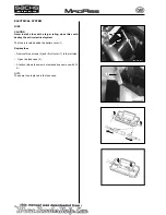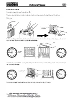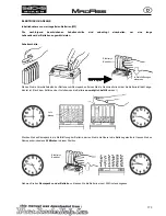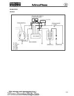
Locking pins
Locking pins
2
1
3
4
5
6
182
Assembly of Indicator/Light Bulb
The front indicator of the MadAss is plugged into the handlebar. The indicator is disassembled by turning the complete indicator
anti-clockwise. A piece of rubber hose (1) pushed over the male thread holds the indicator in the handlebar. When removing the
indicator the rubber hose may remain in the handlebar, so that the rubber needs to be pulled out of the handlebar fi rst and pushed
over the indicator before assembly.
The fi rst series of motorbikes was fi tted with indicators of various lengths, however, only indicators of the short design will be
installed in the future.
Light bulb assembly
In order to disassemble the light bulb (4) the indicator glass (5) should not be removed, but the complete indicator head (6) is to
be unscrewed from the threaded section (2).
Light bulb design
Light bulbs of two different designs are installed as standard. The difference is in the socket receptacle (3). The locking pins are
either offset to each other by 180°, or by 100° (see Fig. 2 und 3).
For spare parts purposes either of the two designs may be used. However, one of the locking pins may have to be cut or fi led off
if required.
Fig. 2 Light bulb, rear view back, 180°
Fig. 3 Light bulb, rear view back, 100°
Design of wiring harness with lamp socket
Lamp sockets and indicator cables were also delivered in two different designs. They differentiate in cable length and colour. The
lamp socket with cable is not interchangeable. However, practice has shown that in case of a fall the lamp socket with cable will
not be damaged and remain fi t for further use.
The indicator head remained the same for both designs.
Cable colours:
Design I:
Orange
= Indicator left
Blue
= Indicator right
Green
=
Ground
Design II:
Black
= Plus
Black/White
=
Ground
ELECTRICAL SYSTEM
Содержание madass
Страница 53: ...50 LUBRICATION SYSTEM...
Страница 111: ...10 12 Nm 10 14 Nm 108 CYLINDER PISTON...
Страница 112: ...109 ZYLINDER KOLBEN...
Страница 129: ...1 2 126 CLUTCH GEARSHIFT LINKAGE Remove the primary drive clutch 1 and clutch center guide 2...
Страница 130: ...127 KUPPLUNG SCHALTGEST NGE Das Prim rantriebsrad 1 und die Kupplungsnaben Lager h lse 2 entfernen...
Страница 191: ...PICK UP KILL SWITCH RPM STOP B R G G G Bl W 188 IGNITION SYSTEM SCHEMA...
Страница 192: ...PICK UP KILLSCHALTER DREHZAHLBEGRENZER Z NDANGLEICHER B R G G G Bl W 189 Z NDSYSTEM DIAGRAM...


