background image

SACHS
Recommends

Printed in Germany                                                                                                                                                                                   2005 04 003

Sachs Fahrzeug- und Motorentechnik GmbH 

·

 Ernst-Sachs-Straße 6

D-90441 Nürn berg 

· 

Tel +49 (0)911 42 31 0 

·

 Fax +49 (0) 911 42 31 405

SACHS
verwendet
und empfi ehlt

Содержание madass

Страница 1: ...SACHS Recommends Printed in Germany 2005 04 003 Sachs Fahrzeug und Motorentechnik GmbH Ernst Sachs Stra e 6 D 90441 N rnberg Tel 49 0 911 42 31 0 Fax 49 0 911 42 31 405 SACHS verwendet und empfiehlt...

Страница 2: ...Repair Instructions No P00 649 008 06 01 000 Edition March 2005 Reparaturanleitung Nr P00 649 008 06 01 000 Ausgabe M rz 2005 Sachs Fahrzeug und Motorentechnik GmbH...

Страница 3: ...o the printer The technical information is intended for master me chanics since its careful and constant observation is a requisite for preserving the operability of the individual assemblies of the m...

Страница 4: ...ister und Mechaniker denn ihre sorgf ltige und st ndige Beachtung ist Voraussetzung f r die Erhaltung der Betriebssicherheit der einzelnen Aggregate des Kraft rades Unabh ngig davon gelten selbstverst...

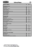
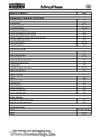
Страница 5: ...Valve clearance 26 28 Carburetor idle speed 28 Air cleaner 30 Adjusting the clutch lever play 32 Checking adjusting the drive chain 34 Brake system 36 38 40 42 Frontwheel 44 Rearwheel 46 Wheel bearin...

Страница 6: ...Z ndkerze 24 25 Ventilspiel 26 29 Vergaser Leerlaufdrehzahl 28 29 Luftfilter 30 31 Kupplungshebelspiel einstellen 32 33 Antriebskette pr fen und einstellen 34 35 Bremsanlage 36 43 Vorderrad 44 45 Hint...

Страница 7: ...0 Cylinder removal cylinder inspection 112 Piston removal piston piston ring inspection 114 116 Connecting rod inspection 116 Piston ring installation piston installation 118 Cylinder installation 120...

Страница 8: ...elle 111 Zylinder ausbauen Zylinder pr fen 112 113 Kolben ausbauen Kolben Kolbenringe pr fen 114 117 Pleuel pr fen 116 117 Kolbenringe einsetzen Kolben einbauen 118 119 Zylinder einbauen 120 121 KUPPL...

Страница 9: ...rankcase assembly 166 ELECTRICAL SYSTEM Fuse 168 Battery charging battery 170 Commissioning battery 172 174 Cockpit speedometer adjustment 176 Speedometer battery change 178 Changing bulbs 180 Assembl...

Страница 10: ...rbelgeh use zusammenbauen 166 167 ELEKTRISCHE ANLAGE Sicherung 168 169 Batterie Batterie laden 171 Inbetriebnahme Batterie 173 175 Cockpit Tachometer einstellen 176 177 Tachometer Batteriewechsel 178...

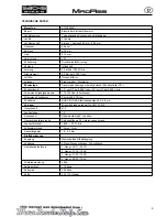
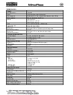
Страница 11: ...onic ignition control CDI Ignition timing 15 before TDC at 2 000 rpm 30 before TDC at 3 500 rpm Pickup coil resistance 110 130 Ohm bl w ground Ignition coils resistance Primary 550 570 Ohm Spark plug...

Страница 12: ...bei 2 000 1 min 30 vor OT bei 3 500 1 min Widerstand Signalgeberspule 110 130 Ohm bl w Masse Widerstand Z ndspulen Prim r 550 570 Ohm Z ndkerze NGK CR7 HSA Elektrodenabstand 0 6 0 8 mm Vergaser Mikun...

Страница 13: ...g 0 35 litres reserve Fuel Unleaded fuel min 91 octane Telescopic fork oil Viscosity SAE 10 W Filling quantity per fork tube 180 cm3 Engine oil Filling quantity SAE 15 W 40 mineral oil API SG or highe...

Страница 14: ...iter inkl 0 35 Liter Reserve Kraftstoff bleifreier Normalkraftstoff ROZ 91 Teleskopgabel l Viskosit t SAE 10 W F llmenge pro Gabelholm 180 cm3 Motor l F llmenge SAE 15 W 40 Mineral l API SG oder h her...

Страница 15: ...tor nut 40 45 Engine oil drain plug 22 25 Valve cover lock 10 12 Chassis Rear wheel axle nut 50 60 Front wheel axle nut 45 55 Swing axle nut 45 55 Disc brake screws 12 14 Front brake calliper bolts 60...

Страница 16: ...er 40 45 lablassschraube 22 25 Ventildeckelverschraubung 10 12 Fahrgestell Hinterachsmutter 50 60 Vorderachsmutter 45 55 Schwingenachsmutter 45 55 Bremsscheibenschrauben 12 14 Bremssattelschrauben vor...

Страница 17: ...side hole 1 X X X X P40 649 050 02 000 390 Spark plug 1 X P40 649 050 02 000 980 Gasket drain plug 1 X X X X P00 935 982 07 25 000 MOTOREX Formula 4T 10W40 1 0 8 Liter 0 8 Liter 0 8 Liter 0 8 Liter P...

Страница 18: ...000 470 O Ring Magnet Sichtdeckel 1 X X X X P40 649 050 02 000 390 Z ndkerze 1 X P40 649 050 02 000 980 labla dichtung 1 X X X X P00 935 982 07 25 000 MOTOREX Formula 4T 10W40 1 0 8 Liter 0 8 Liter 0...

Страница 19: ...lace brake pads I I W W W Adjust rear brake I I I I I Brake fluid Change change every 2 years Brake hoses Check and renew min every 4 years I I I I I Clutch Check and adjust I I I I I Rear suspension...

Страница 20: ...tand I I I I I Bremsbel ge I I W W W Hinterradbremseinstellung I I I I I Bremsfl ssigkeit Wechseln alle 2 Jahre wechseln Bremsschl uche Pr fen alle 4 Jahre erneuern I I I I I Kupplung Pr fen ggf einst...

Страница 21: ...thatmanufacturer name or number point to the outside Lubricate the bearings with oil ATTENTION Do not use compressed air to dry the bearings since this could damage the surface of the bearings When as...

Страница 22: ...CHTUNG ZumTrocknenderLagerniemalsDruckluftverwenden dadie Oberfl che der Lager dadurch besch digt werden k nnte Beim Einbau von Dichtringen 1 darauf achten dass der Herstellername bzw die Nummer nach...

Страница 23: ...olt 11 6 10 12 Drive sprocket bolt 2 6 12 14 TORQUE VALUES TORQUE VALUES FRAME Connection Nm Handle bar holder 22 25 Fastening screws for upper fork bridge 25 28 Fastening screws for lower fork bridge...

Страница 24: ...Kurbelgeh usedeckelschraube 11 6 10 12 Antriebskettenradschraube 2 6 12 14 ANZUSMOMENTE ANZUGSMOMENTE FAHRGESTELL Verbindung Nm Lenkerhalterschraube oben 22 25 Befestigungsschrauben f r obere Gabelbr...

Страница 25: ...ening torques gerneral Nm Srew connection M5 5 6 Srew connection M6 8 10 Srew connection M8 22 25 Srew connection M10 38 42 Tightening torques for plastic connections Nm Srew connection M5 3 5 Srew co...

Страница 26: ...hmomente allgemein Nm Schraubverbindung M5 5 6 Schraubverbindung M6 8 10 Schraubverbindung M8 22 25 Schraubverbindung M10 38 42 Anziehdrehmomente allgemein f r Kunststoffverbindungen Nm Schraubverbind...

Страница 27: ...have square edges and the side electrode 3 should have a constant thickness Discard the spark plug if there is apparent wear or if insulator is cracked or chipped Measure the spark plug gap using a w...

Страница 28: ...e vorweisen Eine offensichtlich verschlissene Z ndkerze muss ausgewechselt werden dies gilt auch f r Risse oder Br che in der Isolierung Den Elektrodenabstand der Z ndkerze mit einer Draht f hlerlehre...

Страница 29: ...d 2 of the left side engine cover Remove the valve adjuster covers 3 Rotate the crankshaft counterclockwise and align the T mark with index mark on the left crankcase Make sure the piston is at TDC on...

Страница 30: ...le im Gegenuhrzeigersinn drehen und die Markierung T mit der Indexmarkierung auf dem linken Kurbelgeh usedeckel ausrichten Sicherstellen da sich der Zylinder im oberen Totpunkt des Verdichtungstaktes...

Страница 31: ...her engine maintenance items have been performed and are within specifications The engine must be warm for accurate idle speed inspection and adjustment Shift the transmission into neutral and place t...

Страница 32: ...alle brigen Motoreinstellungen vorschriftsm ig durchgef hrt worden sind F r eine genaue berpr fung und Einstellung mu der Motor warm sein In den Leerlauf schalten und das Motorrad auf gerader Fl che a...

Страница 33: ...ew the clamp 2 and remove the air cleaner 3 from the carburetor Opening the air filter Remove the three screws 4 Take off the cover 5 Clean the filter case and filter element 6 or replace if necessary...

Страница 34: ...d Luftfilter 3 vom Vergaser ab nehmen Luftfiltereinsatz ffnen Drei Schrauben 4 entfernen Geh usedeckel 5 abnehmen Luftfiltergeh use reinigen und ggf Papierfilter 6 er neuern HINWEIS Vor dem Einbau O R...

Страница 35: ...ew 3 as appropriate Tighten up the lock nut 2 Check the play NOTE If the clutch play cannot be corrected with this adjustment the following adjustment must be made Release the lock nut 2 Tighten setti...

Страница 36: ...en Spiel kontrollieren HINWEIS L t sich das Kupplungsspiel mit dieser Einstellung nicht korri gieren mu folgende Einstellung durchgef hrt werden Kontermutter 2 l sen Einstellschraube 3 ganz eindrehen...

Страница 37: ...e chain sprocket and pinion Adjusting the chain CAUTION How the chain is adjusted affects the rate of wear on the chain and sprocket A too tight adjustment of the chain will cause bearing damages on e...

Страница 38: ...echseln Kette einstellen ACHTUNG Die Ketteneinstellung beeinflusst den Verschlei von Kette und Zahnkranz Eine zu stramm eingestellte Kette kann zu Lagersch den am Motor Hinterrad und vorzeitigem Versc...

Страница 39: ...e lining for wear and the brake system for leaks Only use new brake fluid of specification DOT 4 Brake fluid is exposed to high tempera tures and absorbs moisture from the ambient air NOTE Cover the p...

Страница 40: ...anlageaufDichtheitkontrollieren Nur neue Bremsfl ssigkeit der Spezifikation DOT 4 verwen den Bremsfl ssigkeit ist hohen thermischen Belastungen ausgesetzt und nimmt Feuchtigkeit aus Umgebungsluft auf...

Страница 41: ...ews 3 from the calliper 2 Remove the calliper Remove the holder bolts 4 from the calliper 1 Remove the brake linings 2 Check the lock plate 5 for damage Insert the new brake linings and fasten them wi...

Страница 42: ...ebolzen 4 aus Bremssattel 1 entfernen Bremsbel ge 2 entnehmen Sicherungsblech 5 auf Besch digung berpr fen Neue Bremsbel ge einsetzen und mit dem Haltebolzen befestigen Der Zusammenbau erfolgt sinngem...

Страница 43: ...ng NOTE The brake linings may only be replaced in pairs Use heatproofed lubricant e g copper paste for mechanical movable parts Use screw lock e g Loctite 242 for brake screws Unscrew the bolts 3 and...

Страница 44: ...hselt werden Mechanisch bewegliche Teile mit hitzebest ndigem Schmierfett z B Kupferpaste schmieren Sicherung mit Schraubensicherungsmittel z B Loctite 242 d rchf hren Schrauben 3 losschrauben und Bre...

Страница 45: ...er period of operation adjustment of the brakes is essential due to natural wear of the brake shoe linings Release the lock nut 4 and adjust the nut 5 so that the pedal 3 has reached a guideline of ap...

Страница 46: ...zeit der Bremskl tze muss der Leerweg des Fu bremshebels nachgestellt werden Kontermutter 4 l sen und Mutter 5 soweit auf der Brems stange nachstellen dass am Fu bremshebel 3 ein Ma ca 20 mm erreicht...

Страница 47: ...ating axle 2 and remove the spacer bush 3 Remove the front wheel downwards Installing the front wheel CAUTION Take care not to damage the brake discs and linings 4 while installing them Roll the front...

Страница 48: ...3 abnehmen Vorderrad nach unten herausnehmen Vorderrad einbauen ACHTUNG Bremsscheibe und bel ge 4 beim Einbau nicht besch di gen Vorderrad mit Bremsscheibe vorsichtig zwischen die Gabel holme rollen...

Страница 49: ...the left of the wheel hub is not lost Raise the rear wheel remove the full floating axle 4 with brake support 5 and brake calliper and take off the rear wheel to the back Installing the rear wheel CAU...

Страница 50: ...s 3 an der Radnabe nicht verloren geht Hinterrad anheben Steckachse 4 und Bremsgegenhalter 5 mit Bremssattel entfernen und Hinterrad nach hinten entnehmen Hinterrad einbauen ACHTUNG Bremsscheibe und b...

Страница 51: ...el bearing Remove the rear wheel Remove the brake shoe support Use an internal extractor to pull the wheel bearing 1 out of the bearing seat of the wheel hub 2 Installing the wheel bearing Press the w...

Страница 52: ...aus dem Lagersitz der Radnabe 2 herausziehen Radlager einbauen Radlager 1 in den Lagersitz der Radnabe 2 einpres sen Hinterrad einbauen R der statisch wuchten Entsprechendes Rad in Wuchtvorrichtung e...

Страница 53: ...50 LUBRICATION SYSTEM...

Страница 54: ...51 SCHMIERSYSTEM 1 KIPPHEBELWELLE 2 NOCKENWELLE 3 KOLBEN 4 KURBELWELLE 5 LPUMPE 6 KUPPLUNGSBAUGRUPPE 7 FLIEHKRAFT LFILTER 8 LFILTERSIEB...

Страница 55: ...0 litres at disassembly 0 8 litres at oil change Engine oil Recommended grade Per API SG or higher or also with additional release status ACEA A3 96 CCMC G5 Recommended viscosity Viscosity depends on...

Страница 56: ...nach Zerlegen des Motors 0 8 Liter nach lablassen Motor l Empfohlene Klassen Nach API SG oder h her oder auch mit zus tzlichem Freigabestatus ACEA A3 96 CCMC G5 Empfohlene Viskosit t Viskosit tsklass...

Страница 57: ...od condition and install the drain bolt TORQUE 25 Nm Fill the crankcase with the recommended oil CAPACITY 0 8 litres at oil change Install the oil filler cap dipstick Start the engine and let it idle...

Страница 58: ...25 Nm Das Kurbelgeh use mit dem empfohlenen l f llen F LLMENGE 0 8 Liter nach lablassen Den leinf lldeckel lmess Stab wieder schlie en Den Motor starten und f r 2 bis 3 Minuten im Leerlauf Warmlaufen...

Страница 59: ...se Install the removed parts in the reverse order of removal Fill the engine with recommended oil OIL PUMP REMOVAL NOTE The oil pump can be removed with the engine in the frame Drain the engine oil an...

Страница 60: ...ihenfolge einbauen Den Motor mit dem empfohlenen l bef llen LPUMPE AUSBAUEN HINWEIS Die lpumpe kann bei im Rahmen montierten Motor ausgebaut werden Das Motor l ablassen und den rechten Kurbelgeh usede...

Страница 61: ...aft and inner and outer rotors into the pump body Measure the rotor tip clearance SERVICE LIMIT 0 20 mm 0 008 in Measure the pump body clearance SERVICE LIMIT 0 12 mm 0 005 in Clean all disassembled p...

Страница 62: ...r fen 1 PUMPENDECKEL 2 DECKELDICHTUNG 3 INNENROTOR 4 PUMPENK RPER 5 AUSSENROTOR 6 ROTORWELLE INSPEKTION Rotorwelle Innenrotor und Au enrotor in das Pumpen geh use einbauen Das Spiel an der Rotorspitze...

Страница 63: ...e the cover with the three screws 7 and make sure that the oil pump turns freely without binding INSTALLATION Set the shaft collar 1 into the right crankcase Install a new oil pump gasket 2 and set th...

Страница 64: ...uben 7 festziehen und sicher stellen dass die lpumpe st rungsfrei dreht EINBAUEN Die Wellenh lse 1 in das rechte Kurbelgeh use setzen Eine neue lpumpendichtung 2 einbauen und die lpumpe 3 in das recht...

Страница 65: ...re than one month drain the float bowls Fuel left in the float bowls will cause clogged jets resulting in starting and driveability complaints SPECIFICATIONS Fuel tank capacity 4 6 lit Fuel reserve ca...

Страница 66: ...geh use ablassen Restbenzin in den Schwimmergeh usen f hrt zu verstopften D sen so dass das Anlassen und Fahren des Motors gest rt wird TECHNISCHE DATEN Tankfassungsverm gen 4 6 Liter Reservekraftstof...

Страница 67: ...e compressing the throttle valve spring as shown Remove the throttle valve 2 spring 3 and carburetor top Remove the needle retainer and take out the jet needle from the throttle valve Check the thrott...

Страница 68: ...2 Feder 3 und Vergaseroberteil entfernen Den Nadelhalter entfernen und die D sennadel aus dem Gasschieber herausziehen Den Gasschieber und die D sennadel auf Kratzer oder Verschlei pr fen 1 GASSCHIEB...

Страница 69: ...grip free play Carburetor idle speed CARBURETOR REMOVAL WARNING Gasoline is extremely flammable and is explosive under cer tain conditions Work in a well ventilated area Do not smoke or allow flames...

Страница 70: ...r und unter bestimmten Bedingungen explosiv Arbeiten bei gut bel fteter Umgebung und abgestelltem Motor durchf hren Am Arbeitsplatz und in der N he von gelagertem Benzin nicht rauchen und Flammen oder...

Страница 71: ...ion of the float valve Check the float for damage and fuel in float Remove the main jet 4 Remove the pilot jet 5 Turn the air screw 6 in and record the number of turns before it seats lightly CAUTION...

Страница 72: ...ch digung und Kraftstoff im Innern pr fen Hauptd se 4 und Nadeld se 5 ausbauen Die Gemischregulierschraube 6 eindrehen und die Anzahl der Umdrehungen aufschreiben bis die Schraube leicht sitzt ACHTUNG...

Страница 73: ...ings with compressed air Install the needle jet 1 and main jet 2 Install the throttle stop screw 3 and air screw 4 and return the air screw to its original position as noted during removal Perform an...

Страница 74: ...lasen Nadeld se 1 und Hauptd se 2 einbauen Die Drosselklappen Anschlagschraube 3 und die Gemisch regulierschraube 4 montieren Die Gemischregulierschraube in die vorher notierte Ausgangs stellung zur c...

Страница 75: ...EL INSPECTION Measure the float level with the carburetor inclined 15 45 from vertical so that the float tang just contacts the float valve FLOAT LEVEL 18 0 mm TOOL VERNIER CALLIPER Make sure the floa...

Страница 76: ...bei um 15 bis 45 zur Senkrechten geneigtem Vergaser messen so dass die Schwimmerzunge gerade das Schwimmerventil ber hrt SCHWIMMERSTAND 18 0 mm WERKZEUG ME SCHIEBER Sicherstellen dass sich der Schwim...

Страница 77: ...ion given below CAUTION Damage to the air screw seat will occur if the screw is tightened against the seat AIR SCREW INITIAL OPENING 2 5 Warm up the engine to operating temperature WARNING If the engi...

Страница 78: ...UNG Die Gemischregulierschraube wird besch digt wenn sie gegen den Sitz angezogen wird GEMISCHREGULIERSCHRAUBEN ANFANGS FFNUNG 2 5 Den Motor auf normale Betriebstemperatur Warmlaufen lassen WARNUNGRNU...

Страница 79: ...ck Turn the fuel cock on position RES Open the seal and drain the fuel tank completely Loosen the hose clamps 3 and pull off the fuel hose 4 Remove the fuel cock Clean the sieve 5 Installing the fuel...

Страница 80: ...en Verschluss 2 abschrauben und Kraftstofftank vollst ndig entleeren Schlauchklemme 3 l sen und Kraftstoffschlauch 4 ab ziehen Kraftstoffhahn ausbauen Sieb 5 reinigen Kraftstoffhahn einbauen HINWEIS D...

Страница 81: ...Transmission Shift drum and forks Crankshaft Kick starter spindle SPECIFICATION Engine oil capacity 0 8 lit after draining 1 0 lit after disassembly Engine dry weight 22 kg TORQUE VALUES Engine upper...

Страница 82: ...eh use Getriebe Schattrommel und Gabeln Kurbelwelle Kickstarterwelle TECHNISHE DATEN lmenge 0 8 Liter nach Ablassen 1 0 Liter nach Demontage Leergewicht des Motors 22 kg ANZUGSMOMENTE Obere Motorbefes...

Страница 83: ...lubrication SERVICE DATA Unit mm ITEM STANDARD SERVICE LIMIT Cylinder head Warpage 0 05 Valve seat width 1 0 1 6 Cam height IN 19 105 18 705 EX 19 097 18 697 Rocker arm I D 10 000 10 015 10 10 Rocker...

Страница 84: ...chen WARTUNGSDATEN Einheit mm GEGENSTAND SOLLWERT VERSCHLEISSGRENZE Zylinderkopf Verzug 0 05 Ventilsitzbreite 1 0 1 6 Nockenh he Einlass 19 105 18 705 Auslass 19 097 18 697 Kipphebel I D 10 000 10 015...

Страница 85: ...troubles Incorrect valve adjustment Burnt or bent valves Incorrect valve timing Broken valve spring Worn or damaged valve seat Cylinder head Leaking or damaged head gasket Warped or cracked cylinder...

Страница 86: ...mpression Ventile Falsche Ventileinstellung Ventile verbrannt oder verbogen Falsche Ventilsteuerzeit Ventilfeder gerissen Ventilsitz verschlissen oder besch digt Zylinderkopf Zylinderkopfdichtung undi...

Страница 87: ...it from falling into the cylinder head Remove the valve adjuster covers and loosen the valve adjusters completely Screw the cam sprocket bolts into the camshaft and pull out the camshaft 1 while holdi...

Страница 88: ...lenkettenrad 9 entfernen Die Ventileinstellerdeckel entfernen und die Ventileinsteller vollst ndig l sen Die Nockenwellenkettenradschrauben in die Nockenwelle eindrehen und die Nockenwelle 1 herauszie...

Страница 89: ...wing cam sprocket cylinder head nuts and cylinder head bolt cylinder head cover and gasket cylinder head CYLINDER HEAD DISASSEMBLY Remove the two bolts right side cover and gasket Screw an 8 mm bolt i...

Страница 90: ...l und Dichtung Zylinderkopf 1 ZYLINDERKOPFMUTTERN 2 ZYLINDERKOPFDECKEL 3 ZYLINDERKOPFSCHRAUBE ZYLINDERKOPF ZERLEGEN Zwei Schrauben l sen um rechten Seitendeckel und Dichtung zu entfernen 1 DICHTUNG 2...

Страница 91: ...g seat and valve NOTE Mark all disassembled parts to ensure correct reassembly Remove the stem seals if necessary NOTE Remove the stem seals with new ones whenever they are removed Remove the carbon d...

Страница 92: ...ile markieren um sp ter einen korrekten Einbau sicherzustellen Ggf alle Schaftdichtungen entfernen HINWEIS Ausgebaute Schaftdichtungen m ssen stets durch neue ersetzt werden 1 VENTILFEDER 2 VENTIL 3 F...

Страница 93: ...he free length of the valve spring SERVICE LIMIT 32 mm Cylinder Head Check the spark plug hole and valve area for cracks Check the cylinder head for warpage with a straight edge and a feeler gauge SER...

Страница 94: ...der messen VERSCHLEISSGRENZE 32 mm Zylinderkopf Den Bereich um das Z ndkerzenloch und die Ventilbohrung auf Risse untersuchen Den Zylinderkopf mit einem Richtlineal oder einer F hlerlehre auf Verzug p...

Страница 95: ...bring the clearance within tolerance If so replace the guides as necessary and ream to fit If the stem to guide clearance still exceeds the service limit with new guides replace the valves and guides...

Страница 96: ...st die betreffenden F hrungen auswechseln und zum Einpassen ausreiben Falls das Spiel mit neuer F hrung immer noch die Verschlei grenze berschreitet m ssen sowohl die F hrungen als auch die Ventile au...

Страница 97: ...any metal particles Reface the valve seat VALVE SEAT INSPECTION REFACING VALVE SEAT INSPECTION Clean the intake and exhaust valves thoroughly to remove carbon deposits Apply a light coating of Prussi...

Страница 98: ...zu beseitigen Den Ventilsitz nachschleifen 1 VENTILF HRUNGS REIBAHLE VENTILSITZ BERPR FEN NACHSCHLEIFEN VENTILSITZ BERPR FEN Die Ein und Auslassventile gr ndlich von Kohleresten s ubern Eine d nne Sc...

Страница 99: ...anufacturers operating instructions Use a 45 degree cutter to remove any roughness or irregular ities from the seat NOTE Reface the valve seat with a 45 degree cutter when a valve guide is replaced Us...

Страница 100: ...FMASCHINE Einen 45 Grad Fr ser verwenden um Ungleichm igkeiten vom Sitzring wegzuschleifen HINWEIS Bei neuer Ventilf hrung den Ventilsitz mit einem 45 Grad Fr ser nachschleifen 1 UNGLEICHM SSIGKEITEN...

Страница 101: ...t for good sealing If the contact area is too high on the valve the seat must be lowered using a 32 degree flat cutter If the contact area is too low on the valve the seat must be raised using a 60 de...

Страница 102: ...der Sitz mit einem 32 Grad Flachfr ser gesenkt werden Ist die Kontaktfl che auf dem Ventil zu niedrig muss der Sitz mit einem 60 Grad lnnenfr ser angehoben werden Den Ventilsitz mit einem 45 Grad Fei...

Страница 103: ...r to firmly seat the cotters CAUTION Support the cylinder head above the work bench surface to prevent valve damage Apply clean engine oil to the camshaft and camshaft bearings Install the camshaft in...

Страница 104: ...bank abst tzen um m gliche Besch digung der Ventile zu vermeiden 1 VENTILFEDERZANGE 2 VENTILFEDERZANGEN AUFSATZ Nockenwelle und Lager mit sauberem Motor l bestreichen Die Nockenwelle in den Zylinderko...

Страница 105: ...nstall the cylinder head and a new head cover gasket Position the cylinder head cover with its arrow 1 facing the exhaust side Install the sealing washer 2 copper washer 3 and nuts 4 in the proper loc...

Страница 106: ...f mit neuer Dichtung einbauen 1 DICHTUNG Den Zylinderkopfdeckel so positionieren dass seine Pfeilmarke 1 zur Auslassseite zeigt Dichtungsscheibe 2 Kupferscheibe 3 und Muttern 4 an den entsprechenden P...

Страница 107: ...d camshaft bearings with clean engine oil While holding the rocker arms out of the way install the camshaft into the cylinder head with the cam lobes facing the piston Install the dowel pin into the c...

Страница 108: ...Kipphebel beiseite halten und die Nockenwelle in den Zylinderkopf setzen wobei die Nockenbuckel zum Kolben gerichtet sind 1 NOCKENBUCKEL 2 NOCKENWELLE Den Passstift in die Nockenwelle einsetzen Die O...

Страница 109: ...ION Warm up the engine Stop the engine and remove the spark plug 5 Insert the compression gauge Move the choke lever 7 downward Open the throttle grip fully Crank the engine with the kick starter 8 NO...

Страница 110: ...rze 5 ausbauen Einen Kompressionsmesser einf hren Den Chokehebel 7 nach unten stellen Den Gasdrehgriff voll aufdrehen Den Motor mit dem Kickstarter 8 durchtreten HINWEIS Den Motor solange durchstarten...

Страница 111: ...10 12 Nm 10 14 Nm 108 CYLINDER PISTON...

Страница 112: ...109 ZYLINDER KOLBEN...

Страница 113: ...n clearance 0 010 0 045 0 15 Piston pin O D 12 994 13 000 12 98 Piston to pin clearance 0 002 0 014 0 08 Piston ring End gap Top second 0 15 0 35 0 5 Oil side rail 0 30 0 90 1 1 Piston to ring groove...

Страница 114: ...0 010 0 040 0 15 Kolbenbolzen A D 12 994 13 000 12 98 Spiel Kolben Kolbenbolzen 0 002 0 014 0 08 Kolbenring Sto ffnung Oberster Zweiter 0 05 0 20 0 50 labstreifring Seitenring 0 20 0 90 1 1 Spiel Kol...

Страница 115: ...at right angles to each other SERVICE LIMITS 39 05 mm Measure the piston O D and calculate the piston to cylinder clearance using the maximum cylinder I D measurement SERVICE LIMIT 0 15 mm Measure th...

Страница 116: ...Kolbenbewegung sowie in zwei Richtungen im rechten Winkel zueinander VERSCHLEISSGRENZE 39 05 mm Den Kolben Au endurchmesser messen und das Spiel zwischen Kolben und Zylinder berechnen wobei der gr te...

Страница 117: ...te side with your finger Remove the piston PISTON PISTON RING INSPECTION Measure the piston ring to groove clearance with a feeler gauge SERVICE LIMITS Top 0 12 mm Second 0 12 mm Measure the piston O...

Страница 118: ...ntfernen 1 KOLBEN 2 KOLBENBOLZEN SICHERUNGSRING 3 KOLBENBOLZEN KOLBEN KOLBENRING BERPR FEN Das Spiel zwischen Kolbenring und Ringnut mit einer F hlerlehre messen VERSCHLEISSGRENZE Oberste Nut 0 12 mm...

Страница 119: ...I D SERVICE LIMIT 13 06 mm Calculate the piston pin to connecting rod clearance SERVICE LIMIT 0 03 mm Remove the piston rings NOTE Do not damage the rings during removal Inspect the piston ring for d...

Страница 120: ...SGRENZE 13 06 mm Das Spiel zwischen Kolbenbolzen und Pleuelstange berechnen VERSCHLEISSGRENZE 0 03 mm Die Kolbenringe entfernen HINWEIS Darauf achten die Ringe nicht zu besch digen Die Kolbenringe auf...

Страница 121: ...talla tion After Installation the piston rings should be free to rotate in the grooves Do not interchange the top ring with the second ring Space the piston ring end gaps 120 0 apart Do not align the...

Страница 122: ...zweiten Kolbenring verwechseln Die Kolbenringsto fugen um 120 0 versetzt anordnen Die Sto fugen der labstreifring Seitenringe nicht miteinander ausrichten 1 OBERSTE NUT 2 ZWEITE NUT 3 LABSTREIFNUT 4...

Страница 123: ...r gasket O ring and the dowel pins NOTE Make sure that the oil orifice is not clogged Coat the cylinder and piston rings with clean engine oil an install the cylinder NOTE Be careful not to damage the...

Страница 124: ...lende nicht verstopft Den Zylinder und die Kolbenringe mit sauberem Motor l bestreichen und den Zylinder einbauen Hinweis Beim Einbau nicht die Kolbenringe besch digen 1 DICHTUNG 2 PASS STIFTE 3 O RIN...

Страница 125: ...930 20 950 20 90 Primary drive gear I D 21 000 21 021 21 05 TORQUE VALUES Clutch lock nut 40 45 Nm Shift drum stopper arm bolt 10 Nm Shift drum stopper plate bolt 14 20 Nm Crankcase cover bolt 8 12 N...

Страница 126: ...5 ANZUGSMOMENTE Kupplungssicherungsmutter 40 45 Nm Schalttrommel Anschlagarmschraube 10 Nm Schalttrommel Anschlagblechschraube 14 20 Nm Kurbelgeh usedeckelschraube 8 12 Nm WERKZEUGE Spezialwerkzeug Ku...

Страница 127: ...le 2 Remove the kick starter pedal 3 Remove eight screws and take off the right crankcase cover 4 Remove the gasket 5 and two dowel pins 6 CLUTCH REMOVAL Remove the clutch outer cover 7 by removing th...

Страница 128: ...tfernen Die acht Schrauben entfernen und den rechten Kurbelge h usedeckel 4 abnehmen Die Dichtung 5 und die zwei Passstifte 6 entfernen KUPPLUNG AUSBAUEN Vier Schrauben 8 entfernen und Kupplungsaussen...

Страница 129: ...1 2 126 CLUTCH GEARSHIFT LINKAGE Remove the primary drive clutch 1 and clutch center guide 2...

Страница 130: ...127 KUPPLUNG SCHALTGEST NGE Das Prim rantriebsrad 1 und die Kupplungsnaben Lager h lse 2 entfernen...

Страница 131: ...ar 1 Remove the collar 3 from the crankshaft CLUTCH DISASSEMBLY Remove the set ring 1 Remove the clutch plates 2 friction discs and clutch center 3 Remove the damper springs 4 Separate the drive plate...

Страница 132: ...von der Kurbelwelle entfernen KUPPLUNG DEMONTIEREN Den Setzring 1 entfernen Die Kupplungs Stahl und Reibscheiben 2 die Antriebs zahnrad Au enscheibe 3 und die Kupplungs Mittenscheibe ausbauen Die D m...

Страница 133: ...8 Set spring 9 Damper spring 10 Clutch spring INSPECTION Friction discs Replace the friction discs if they show signs of scoring or discoloration Measure each friction disc thickness SERVICE LIMITS Di...

Страница 134: ...herungsring 9 D mpferfeder 10 Kupplungsfeder INSPEKTION Reibscheiben Reibscheiben mit Riefenbildung und Verf rbung m ssen erneuert werden Die Dicke der Reibscheiben messen Verschlei grenze Scheibe 4 u...

Страница 135: ...er guide O D SERVICE LIMITS Primary drive gear I D 21 05 mm Center guide O D 20 90 mm Clutch Spring Measure each clutch spring free length SERVICE LIMIT 17 5 mm CLUTCH ASSEMBLY Install the four clutch...

Страница 136: ...esser berpr fen VERSCHLEISSGRENZEN Prim rantriebsrad I D 21 05 mm Kupplungsnaben Lagerh lsen A D 20 90 mm Kupplungsfedern Die frei L nger der einzelnen Kupplungsfedern messen VERSCHLEISSGRENZE 17 5 mm...

Страница 137: ...4 4 4 4 3 1 2 134 CLUTCH GEARSHIFT LINKAGE Install the assembly 1 into the clutch outer 2 Install the set ring 3 Install the clutch damper springs 4...

Страница 138: ...135 KUPPLUNG SCHALTGEST NGE Zusammenbau 1 in Kupplungs Au enscheibe 2 einsetzen Sicherungsring 3 montieren Kupplungs D mpferfedern 4 montieren...

Страница 139: ...arm 2 and spring 3 Remove the gearshift pedal Hold the gearshift spindle claw 4 down and pull out the gearshift spindle 5 Remove the stopper plate bolt 6 and the plate 7 ASSEMBLY Install the gearshif...

Страница 140: ...Schaltpedal entfernen Die Schaltspindelklaue 4 niederhalten und die Schaltspindel 5 herausziehen Die Anschlagplattenschraube 6 l sen und die Anschlagplatte 7 entfernen ZUSAMMENBAUEN Das Schaltgest nge...

Страница 141: ...nstall the gearshift spindle 3 and stopper arm 4 TORQUE Stopper arm bolt 10 Nm Stopper plate bolt 17 Nm CLUTCH INSTALLATION Install the collar 1 onto the crankshaft Install the primary driven gear 2 a...

Страница 142: ...und den Anschlagarm 4 einbauen ANZUGSMOMENT Schraube des Anschlagarms 10 Nm Schraube der Anschlagplatte 17 Nm KUPPLUNG EINBAUEN Den Ring 1 auf den Kubelwellenzapfen aufstecken Das Prim rantriebsrad 2...

Страница 143: ...sembly 3 NOTE Install a new lock washer 4 Install the plain washer 5 with the OUTSIDE mark facing out Hold the clutch outer with the clutch outer holder Tighten the lock nut 6 with the lock nut wrench...

Страница 144: ...setzen Die Anlaufscheibe 5 mit der Markierung OUTSIDE nach au en weisend einbauen DieKupplungsau enscheibemitdemKupplungsau enscheiben Halter halten Die Sicherungsmutter 6 mit dem Sicherungmutternschl...

Страница 145: ...n the two dowel pins 4 into the crankcase and use a new gasket 5 Clean the oil filter screen 6 and install into the crankcase RIGHT CRANKCASE COVER INSTALLATION Install the crankcase cover 7 using eig...

Страница 146: ...as Kurbelgeh use einsetzen und eine neue Dichtung 5 verwenden lsieb 6 reinigen und in das Kurbelgeh use einsetzen RECHTEN KURBELGEH USEDECKEL EINBAUEN Kurbelgeh usedeckel 7 aufsetzen und mit acht Schr...

Страница 147: ...chain tensioner Tensioner spring free length 111 0 106 0 Push rod 0 D 11 985 12 000 11 94 TORQUE VALUES Flywheel nut 40 45 Nm Sealing bolt 25 Nm Left crankcase cover bolt 10 Nm TOOLS Common Universal...

Страница 148: ...SGRENZE Nockenkettenspanner Freie L nge der Spannfeder 111 0 106 0 Druckstangen A D 11 985 12 000 11 94 ANZUGSMOMENTE Schwungradmutter 40 45 Nm Dichtungsschraube 25 Nm Linke Kurbelgeh usedeckelschraub...

Страница 149: ...uller M28x1 K09930 34951 000 Remove the flywheel using the flywheel puller Remove the woodruff key from the crankshaft CAM CHAIN TENSIONER INSPECTION Remove bolt 1 Measure the spring free length Servi...

Страница 150: ...chwungrad mit dem Polradabzieher abziehen Den Federkeil von der Kurbelwelle entfernen STEUERKETTENSPANNER BERPR FEN Verschlu schraube 1 entfernen Die freie Federl nge messen Verschlei grenze 106 mm Di...

Страница 151: ...Countershaft O D C1 19 959 19 980 19 94 Gearshift fork I D 34 000 34 025 34 14 Claw thickness 4 86 4 94 4 60 Gearshift drum O D 33 950 33 975 33 93 TORQUE VALUE Shift drum bolt 12 Nm TOOLS Special Un...

Страница 152: ...n A D C1 19 959 19 980 19 94 Schaltgabel I D 34 000 34 025 34 14 Klauenst rke 4 86 4 94 4 60 Schalttrommel A D 33 950 33 975 33 93 ANZUGSMOMENTE Schalttrommelschraube 12 Nm WERKZEUGE Spezialwerkzeug U...

Страница 153: ...equired parts Remove the cam chain Loosen the screw 1 remove the rubber cap 2 gearshift drum bolt 3 and moving contact 4 Remove the crankcase bolts Place the crankcase on the work bench Pry out the ci...

Страница 154: ...Gummikappe 2 abziehen die Schalt trommelschraube 3 l sen und den Schleifkontakt 4 entfernen Die Kurbelgeh useschrauben herausdrehen Das Kurbelgeh use auf eine Werkbank setzen Den Sicherungsring an de...

Страница 155: ...TER Separate the right crankcase from the left crankcase Remove the gasket and dowel pins CRANKSHAFT INSPECTION Remove the crankshaft from the left crankcase Measure the connecting rod big end side cl...

Страница 156: ...von der linken Kurbelge h useh lfte trennen Die Dichtung und die Passstifte entfernen 1 DICHTUNG 2 PASS STIFTE KURBELWELLE PR FEN Die Kurbelwelle aus der linken Kurbelgeh useh lfte entfernen 1 KURBELW...

Страница 157: ...ger The outer race should turn smoothly and quietly Also check that the bearing inner race fits tightly on the crankshaft Replace the crankshaft bearing if the outer race does not turn smoothly quietl...

Страница 158: ...ehen Sicherstellen dass der Lagerinnenlaufring fest an der Kurbelwelle ansitzt Das Kurbelwellenlager auswechseln wenn der Au enlaufring nicht leise und sauber dreht oder zu locker an der Kurbelwelle s...

Страница 159: ...move the circlips and remove the kick starter pinion and friction spring Check the disassembled parts for damage and excessive wear and replace them if necessary Assemble the kick starter as shown Ins...

Страница 160: ...loshebeln und das Ritzel und die Reibfeder entfernen 1 SICHERUNGSRINGE 2 REIBFEDER 3 RITZEL Die zerlegten Teile auf Besch digung und Verschlei untersuchen und ggf auswechseln Den Kickstarter wie geze...

Страница 161: ...sion gears Remove the gears from the mainshaft and countershaft INSPECTION Measure the mainshaft and countershaft O D SERVICE LIMITS M2 16 95 mm 0 667 in C1 16 94 mm 0 667 in Check each gear for wear...

Страница 162: ...und Vorgelegewelle abziehen 1 SCHALTTROMMELGRUPPE 2 HAUPTWELLENGRUPPE 3 VORGELEGEWELLENGRUPPE BERPR FEN Die Au endurchmesser von Hauptwelle und Vorgelegewelle messen VERSCHLEISSGRENZEN M2 16 95 mm C1...

Страница 163: ...asure the gearshift drum O D SERVICE LIMIT 33 93 mm 1 336 in Check the guide pins and shift forks for wear or damage Measure the shift fork I D SERVICE LIMIT 34 14 mm 1 344 in Measure the shift fork c...

Страница 164: ...RPR FEN Die Schalttrommel auf Verschlei und Besch digung ber pr fen Den Schalttrommel A D messen VERSCHLEISSGRENZE 33 93 mm Die F hrungsbolzen und die Schaltgabeln auf Verschlei und Besch digung berpr...

Страница 165: ...he oil seal and drive out the countershaft bearing Drive a new bearing into the left crankcase TOOLS Driver Attachment 37 x 40 mm Pilot 17 mm Apply grease to the lip of a new oil seal and install it i...

Страница 166: ...austreiben Ein neues Lager in die linke Kurbelgeh useh lfte eintreiben WERKZEUGE Treibdorn Aufsatz 37 x 40 mm F hrung 17 mm 1 LAGER Fett auf die Lippe des neuen Wellendichtrings auftragen und in das...

Страница 167: ...oil Assemble the countershaft and mainshaft NOTE Set the circlip in the groove properly 1 24 Teeth 2 27 Teeth 3 31 Teeth 4 36 Teeth 5 Countershaft 6 11 Teeth 7 Mainschaft 8 16 Teeth 9 20 Teeth 10 23 T...

Страница 168: ...auptwelle zusammenbauen HINWEIS Die Sicherungsringe korrekt in die Nut einsetzen 1 NEUTRASCHALTER ROTOR 1 24 Z hne 2 27 Z hne 3 31 Z hne 4 36 Z hne 5 Vorgelegewelle 6 11 Z hne 7 Hauptwelle 8 16 Z hne...

Страница 169: ...rn in two or more steps Install the moving contact 1 and shift drum bolt 2 Tighten the bolt TORQUE 12 Nm Check the O ring 3 and replace if necessary Install the neutral switch 4 carefully and fix with...

Страница 170: ...hleifkontakt 1 mit der Schalttrommelschraube 2 einbauen Die Schraube festziehen ANZUGSMOMENT 12 Nm Den O Ring 3 berpr fen und ggf ersetzen Neutralschalter 4 vorsichtig einsetzen und mit Platte und Sch...

Страница 171: ...ld destroy the entire electrical system The fuse is located behind the battery cover 1 Replace fuse Remove three screws 2 and lift off cover 1 to the left side Open the fuse case 3 A faulty or blown f...

Страница 172: ...e elektrische Anlage zerst ren Die Sicherung befindet sich hinter der Batterieverkleidung 1 Sicherung auswechseln Drei Schrauben 2 entfernen und Verkleidung 1 nach links abnehmen Sicherungsgeh use 3 f...

Страница 173: ...es to direct sunlight Discharged bat teries can freeze so they must be stored in a place where the temperature remains above 0 C Professional maintenance charging and storage will in crease the lifesp...

Страница 174: ...t ungesch tzt dem direkten Tageslicht aus setzen Entladene Batterien k nnen einfrieren deshalb Batterien in einem Raum mit ber 0 C lagern Sachgem e Wartung Ladung und Lagerung erh hen die Lebensdauer...

Страница 175: ...attery once the alumini um foil has been removed the battery must be filled immediately Insert the acid pack into the filler opening of the battery and allow the acid to run into the battery keep the...

Страница 176: ...en Sie bis die S ure in die Batterie gelaufen ist lassen Sie den S urepack mindestens 20 Minuten in dieser Position Nehmen Sie den S urepack von der Batterie und lassen Sie die Batterie erneut 20 Minu...

Страница 177: ...voltage is still lower than 12 5 volt the battery must be recharged If the battery voltage the second charging cycle is still lower than 12 5 volt the battery must be replaced If the motorcycle remai...

Страница 178: ...ng immer noch kleiner als 12 5 Volt muss die Batterie erneut nachgeladen werden Liegt die Batteriespannung nach zweimaligem Laden immer noch unter 12 5 Volt muss die Batterie ersetzt werden Wird das M...

Страница 179: ...DST to clock CLK or Button A press once set up from clock CLK to odometer DST Speedometer time adjustment Button B press once the clock CLK appears the time can be set Button B press once the hour si...

Страница 180: ...z hler DST auf Uhrzeit CLK oder Taste A 1 x Dr cken Umstellung von Uhrzeit CLK auf Kilometerz hler DST Tachometer Uhrzeit einstellen Taste B 1 x Dr cken die Uhrzeit CLK erscheint die Uhrzeit kann eing...

Страница 181: ...Remove the screws 1 and take off the speedometer Remove the screws 2 and take off the cover 3 Remove the batteries 4 and replace against new once type AG 13 Set in the batteries with the plus terminal...

Страница 182: ...den Schrauben 1 entfernen und Tacho abnehmen Schrauben 2 entfernen und Deckel 3 abnehmen Knopfzellen 4 entnehmen und gegen neue Knopfzellen Typ AG 13 austauschen Knopfzellen mit Pluszeichen nach oben...

Страница 183: ...ver 5 from the headlight Release the holder clamp 6 and remove the bulb 7 Pull the position light 3 with the bulb holder carefully out of the headlight housing Assemble in reverse order NOTE When asse...

Страница 184: ...lteb gel 6 zur Seite schwenken und Gl hlampe 7 ent nehmen Standlicht Gl hlampe 3 mit Fassung aus dem Scheinwer fergeh use nehmen Der Einbau erfolgt in umgekehrter Reihenfolge HINWEIS Halteb gel 6 zum...

Страница 185: ...unscrewed from the threaded section 2 Light bulb design Light bulbs of two different designs are installed as standard The difference is in the socket receptacle 3 The locking pins are either offset t...

Страница 186: ...ten Gl hlampen werden serienm ig in zwei unterschiedlichen Ausf hrungen verbaut Der Unterschied ist die Sockelaufnahme 3 Die Verriegelungsbolzen sind entweder um 180 oder um 100 versetzt angeordnet si...

Страница 187: ...carefully out of the handlebar and hold the thread bolt 3 with a pair of pliers Release the light case Push the bulb 5 back and release it by turning to the left Take the bulb out Rear Release the nu...

Страница 188: ...h benutzen Vorne Blinkergeh use 2 vorsichtig aus dem Lenkergriff ziehen und Gewindeschraube 3 mit Zange festhalten Blinkergeh use abschrauben Gl hlampe 5 entriegeln und heraus nehmen Hinten Mutter 4 l...

Страница 189: ...he tyres filled at the correct pressure Measure the distance from the floor to the centre of the head lamp and mark the height on the wall with a cross Draw a second cross 12 cm beneath the first cros...

Страница 190: ...er vor einer hellen Wand auf ebenem Boden aufgestellt Der Abstand vom Boden bis zur Scheinwerfermitte wird auf die Wand bertragen und mit einem Kreuz markiert 12 cm unter diesem Kreuz wird ein zweites...

Страница 191: ...PICK UP KILL SWITCH RPM STOP B R G G G Bl W 188 IGNITION SYSTEM SCHEMA...

Страница 192: ...PICK UP KILLSCHALTER DREHZAHLBEGRENZER Z NDANGLEICHER B R G G G Bl W 189 Z NDSYSTEM DIAGRAM...

Страница 193: ...or NORMAL 3 Disconnect the CDI unit connector from the CDI unit and test for system components at CDI unit 5P connector ABNORMAL 3 1 Check the individual component s NORMAL NORMAL ABNORMAL Open or sho...

Страница 194: ...2 Den Anschluss der CDI Einheit auf festen Sitz pr fen UNNORMAL Anschluss lose NORMAL 3 Den Anschluss der CDI Einheit trennen und die Systemkomponenten am 5 poligen Stecker p rfen UNNORMAL 3 1 Die ei...

Страница 195: ...ndard Ignition coil primary Black Yellow Green circa 1 Signal generator coil pick up Blue white green circa 150 Exciter coil Black red green circa 550 Ignition switch Black white green There should be...

Страница 196: ...Sollwert Z ndspule prim r Schwarz gelb gr n ca 1 Signalgeberspule Pickup Blau wei gr n ca 150 Erregerspule Schwarz rot gr n ca 550 Z ndschalter Schwarz wei gr n Bei OFF muss Stromdurchgang vorliegen...

Страница 197: ...r continuity should be close to the speci fied values Tool Pocket tester Tester knob indication x 1 range PRIMARY COIL INSPECTION Measure the resistance between the terminals RESISTANCE circa 1 at 20...

Страница 198: ...wa folgende Ohmwerte Anzeige x 1 Bereich PRIM RSPULE BERPR FEN De Widerstand zwischen den Klemmen messen WIDERSTAND ca 1 bei 20 C Die Z ndspule auswechseln wenn der Widerstand nicht der Vorschrift ent...

Страница 199: ...re terminal and ground RESISTANCE circa 150 If the resistance is out of the specification replace the alternator IGNITION TIMING INSPECTION NOTE The Capacitive Discharge Ignition CDI system is factory...

Страница 200: ...icht die Lichtmaschine auswechseln Z NDZEITPUNKT BERPR FEN HINWEIS Das Hochspannungs Kondensatorz ndsystem HKZ CDI wurde werkseitig eingestellt und erfordert keine Nach stellung Es werden an dieser St...

Страница 201: ...OUT CLUTCH SWITCH B R Black Red B W Black White B Y Black Yellow Bl W Blue White G R Green Red G Y Green Yellow Y W Yellow White B Black Bl Blue Br Brown G Green Gr Grey LB Light Blue LG Light Green O...

Страница 202: ...OHNE KUPPLUNGSSCHALTER B Schwarz Bl Blau Br Braun G Gr n Gr Grau LB Hellblau LG Hellgr n O Orange R Rot Y Gelb B R Schwarz Rot B W Schwarz Wei B Y Schwarz Gelb Bl W Bau Wei G R Gr n Rot G Y Gr n Gelb...

Страница 203: ...TH CLUTCH SWITCH B R Black Red B W Black White B Y Black Yellow Bl W Blue White G R Green Red G Y Green Yellow Y W Yellow White B Black Bl Blue Br Brown G Green Gr Grey LB Light Blue LG Light Green O...

Страница 204: ...N MIT KUPPLUNGSSCHALTER B Schwarz Bl Blau Br Braun G Gr n Gr Grau LB Hellblau LG Hellgr n O Orange R Rot Y Gelb B R Schwarz Rot B W Schwarz Wei B Y Schwarz Gelb Bl W Bau Wei G R Gr n Rot G Y Gr n Gelb...

Страница 205: ...park plug Clean and dry or replace Defective ignition coil Replace Open or short in high tension cord Replace Defective pick up coil or CDI unit Replace No fuel reaching a carburetor Clogged or defect...

Страница 206: ...er Kurzschluss im Hochspannungskabel Ersetzen Ansprechspule oder Z ndeinheit defekt Ersetzen Kraftstoff gelangt nicht zum Vergaser Schwimmerventil verstopft oder defekt Reinigen Ersetzen Vergaser Nade...

Страница 207: ...lace Noise seems to come from the crankshaft Rattling bearing Replace Worn or burnt crank pin bearing Replace Worn or burnt ball bearing Replace Noise seems to come from the transmission Worn or rubbi...

Страница 208: ...urbelwelle zu kommen Lager klappern Ersetzen Lagerzapfen f r Pleuel verschlissen oder ausgebrannt Ersetzen Kugellager verschlissen oder ausgebrannt Ersetzen Ger usch scheint von Getriebe zu kommen Zah...

Страница 209: ...et Clean Defective generator Replace Engine runs poorly in high speed range Weak valve spring Replace Worn camshaft Replace Insufficient spark plug gap Regap or replace Ignition not advanced sufficien...

Страница 210: ...en Generator defekt Ersetzen Motor l uft schlecht bei h herer Drehzahl Ventilfedern erm det Ersetzen Nockenwelle ausgeschlagen Ersetzen Z ndkerze Elektrodenabstand ungen gend Einstellen Ersetzen Venti...

Страница 211: ...or Starting difficulty Clogged starter jet Clean Clogged starter jet passage Clean Air leaking from joint between starter body and carburetor Tighten adjust or replace gasket Air leaking from carburet...

Страница 212: ...aser Startschwierigkeit Starterd se verstopft Reinigen Durchgang der Starterd se verstopft Reinigen Verbindung zwischen Kaltstart und Vergaser undicht Nachziehen Einstellen Dichtung ersetzen Verbindun...

Страница 213: ...or Generator does not charge Open or short in lead wires or loose lead connections Repair replace or connect properly Shorted grounded or open stator coil Replace Shorted or punctured regulator rectif...

Страница 214: ...f Luftgemisch zu mager Vergaser einstellen Generator l dt nicht Leitungen gebrochen lose oder Kurzschluss Reparieren ersetzen oder korrekt anschliessen Kurzschluss Masseverbindung oder gebrochene Lich...

Страница 215: ...Check if the battery will be charged by running engine Head light bulbs blown all the time Only for vehicles without clutch switch Diode defect or without contact Remove the diode and connect the cont...

Страница 216: ...laden wird wenn der Motor l uft Scheinwerferbirnen brennen st ndig durch Nur Fahrzeuge ohne Kupplungsschalter Diode defekt oder nicht gebr ckt Diode entfernen und Kontakte zusammenschlie en damit Regl...

Страница 217: ...if necessary Battery defect Replace the battery if it can not be charged Battery runs down quickly Incorrect charging method Check generator IC regulator or rectifier circuit connections and make nece...

Страница 218: ...stauschen Batterie defekt Batterie austauschen wenn diese sich nicht laden l sst Batterie entl dt sich schnell Falscher Ladevorgang Generator IC Regler oder Gleichrichter Strom kreis pr fen und notwen...

Отзывы: