


ROYAL ENFIELD WORKSHOP MANUAL
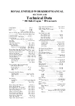
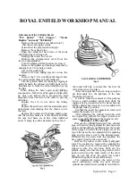
6. Removal of the Cylinder Head
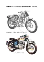
"350 Bullet," "350 Clipper," "Works
Replica" and early "500 Bullet"
Remove the petrol tank (see Subsection 5).
Disconnect the engine steady.
Disconnect the plug lead and oil pipe.
Remove the exhaust pipe.
Push the carburettor back clear of the studs
after removing the fixing nuts.
Remove the rocker box covers.
Remove the decompressor cable from the
lever on the handlebar.
Turn the engine until both valves are closed.
Remove the rockers and bearings complete by
undoing four 1/4 in. nuts on each.
Lift out the push rods.
Remove six nuts, taking care not to lose the
washers.
Remove the 1/4 in. nut above the tappet chest
to avoid possible damage to the crankcase.
Lift the cylinder head off the barrel, tapping it
gently beneath the exhaust and inlet ports with a
hide hammer to break the carbon seal. Do not tap
the fins.
When fitting the head again, apply jointing
compound to both sides of the gasket, replace the
six nuts and tighten them progressively and
diagonally from one side to the other to prevent
distortion.
Replace the 1/4 in. nut above the timing
chest.
Replace the push rods with the adjustable parts
downwards, remembering that the shorter rod is
the inlet.
Replace the rockers and bearings, making sure
that the oil feed holes are at the bottom and that
the caps and bases are in line when tightened
down. A sharp tap with a hammer on the end of
the rocker will help to ensure this. See that the
valve stem caps are in place.
After the engine has been run long enough to
get thoroughly hot, the tightness of the nuts
should be rechecked.
It will be found convenient for this purpose
to use a small auxiliary petrol tank while the
engine is being warmed up on the stand, because
all the cylinder head nuts are not accessible with
the proper tank in position.
See that the rocker box gaskets are intact and
replace the rocker box covers.
After tightening the cylinder head nuts with
the engine hot, recheck the tappet clearance at
some convenient time when the engine is cold.
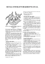
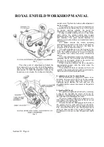
"500 Bullet," 1959 onwards
Remove the cylinder head steady bar, exhaust
pipe, carburettor, plug lead and the decompressor
cable at the handlebar end. Disconnect the rocker
oil feed pipes. Unscrew the five long nuts on the
top of the head, the nut adjacent to the sparking
plug and the sleeve nut by the decompressor.
Withdraw the five studs from the crankcase the
have squared ends to take a spanner.
Remove the rocker covers, rockers and push
rods. The rockers are removed by undoing the
nuts at either end; one of these nuts is bored and
tapped to take the oil union. Slide out the
spindle, taking care that the spring washer at the
push rod end and the plain washer at the other
end do not fall down the push rod tunnel.
Withdraw the push rods and lift the head.
For replacement reverse the order of the
above instructions. Make the joint between
cylinder head and barrel carefully as described in
Section C14 Page 4
the foregoing paragraph. Replace the push rods
and the five long studs in the crankcase,
tightening these very carefully. Replace all the
securing nuts, tightening them progressively to
avoid distortion.
Replace the rocker spindles, inserting them
through the box, through the spring washer held
at the push rod end, through the rocker and the
plain washer at the valve end and through the
other side of the rocker box. Put on the nuts, test
the rockers for freedom, replace the oil unions
and the rocker box covers. Deal with the sparking
plug, carburettor, exhaust pipe, decompressor
cable and head steady and so complete the
assembly.
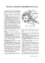
7. Removal of the Valves
Remove the cylinder head and rockers (see
Subsection 6).
Prise away the hardened steel thimble or end
cap where fitted. If this has stuck it can be
removed by means of a screwdriver.
Using a suitable compressing tool, compress
the valve springs and remove the split conical
collets from the end of the valve stem.
Slacken back the compressing tool and release
the springs.
Withdraw the valve and place its springs, top
spring collar (and bottom collar if it is loose), the
end cap and split conical collets together in order
that they may be reassembled with the valve from
which they were removed.
Deal similarly with the other valve in the head.
If the valve will not slide easily through the valve
guide, remove any slight burrs on the end of the
valve stem with a carborundum stone. If the
burrs are not removed and the valve is forced out,
the guide may be damaged.
8. Removal of the Rockers
See Subsection 6.
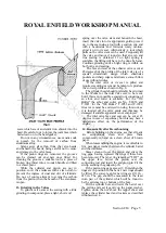
9. Removal of the Valve Guides
To remove the valve guides from the head two
special tools are required which can easily be made.
The first is a piece of tube with an internal bore
of not less than 7/8 in.
The second is a mandrel about 4 in. long, made
from 9/16 in. diameter bar with the end turned
down to 11/32 in. diameter for 1/2 in.
Support the cylinder head on the tube which fits
over the collar of the valve guide. Using the
mandrel, force the guide out of the head with a hand
press or by using a hammer.
To fit a new guide, support the head at the correct
angle and use a hand press and the same mandrel. If
a hand press is not available and the guide is replaced
by a hammer, use the mandrel to prevent damage to
the guide.
It is necessary to recut the valve seat to the
correct profile and grind in the valve after a guide
has been replaced.
10. Removal of the Cylinder Barrel
Remove the Cylinder Head (see Subsection 6).
Put the piston at bottom dead centre.
Remove the 1/4 in. nut above the tappet chest
and lift the barrel off.
When replacing the cylinder barrel, clean off the
joint faces and fit a new paper washer.
11. Removal of the Piston
Remove the cylinder head and cylinder barrel (see
Subsections 6 and 10).
With the tang of a file remove the wire circlip
retaining the gudgeon pin on the timing side.
Extract the gudgeon pin using Special Tool No.
E.5477 (with adaptor if necessary), having first
marked the pin so that it, and the piston, may be
replaced the same way round, i.e. split skirt to the
front.
During this operation put a piece of clean rag in
the top of the crankcase to prevent foreign matter
getting in. In particular, take care not to drop the
circlip in the crankcase.
12. Decarbonising
Having removed the cylinder head as described in
Subsection 6, scrape away all carbon, with a suitable
tool, bearing in mind that you are dealing with
aluminium which is easily damaged. Scrape gently to
avoid scoring the combustion chamber or the valve
www.hitchcocksmotorcycles.com
Содержание 350 BULLET 1956
Страница 3: ...ROYAL ENFIELD WORKSHOP MANUAL 350 BULLET 1961 w w w h i t c h c o c k s m o t o r c y c l e s c o m ...
Страница 5: ...ROYAL ENFIELD WORKSHOP MANUAL 500 BULLET 1956 w w w h i t c h c o c k s m o t o r c y c l e s c o m ...
Страница 7: ...ROYAL ENFIELD WORKSHOP MANUAL w w w h i t c h c o c k s m o t o r c y c l e s c o m ...
Страница 21: ...ROYAL ENFIELD WORKSHOP MANUAL 350 CLIPPER 1958 w w w h i t c h c o c k s m o t o r c y c l e s c o m ...
Страница 23: ...ROYAL ENFIELD WORKSHOP MANUAL Section E1 Page 2 w w w h i t c h c o c k s m o t o r c y c l e s c o m ...
Страница 28: ...ROYAL ENFIELD WORKSHOP MANUAL Section F4 Page 3 w w w h i t c h c o c k s m o t o r c y c l e s c o m ...
Страница 30: ...ROYAL ENFIELD WORKSHOP MANUAL Section F4 Page 5 w w w h i t c h c o c k s m o t o r c y c l e s c o m ...
Страница 42: ...ROYAL ENFIELD WORKSHOP MANUAL Section H5 Page 1 w w w h i t c h c o c k s m o t o r c y c l e s c o m ...
Страница 57: ...ROYAL ENFIELD WORKSHOP MANUAL w w w h i t c h c o c k s m o t o r c y c l e s c o m ...
Страница 69: ...ROYAL ENFIELD WORKSHOP MANUAL w w w h i t c h c o c k s m o t o r c y c l e s c o m ...
Страница 71: ...ROYAL ENFIELD WORKSHOP MANUAL Section M2 Page 2 w w w h i t c h c o c k s m o t o r c y c l e s c o m ...
Страница 72: ...ROYAL ENFIELD WORKSHOP MANUAL Section M2 Page 3 w w w h i t c h c o c k s m o t o r c y c l e s c o m ...
Страница 73: ...ROYAL ENFIELD WORKSHOP MANUAL Section M2 Page 4 w w w h i t c h c o c k s m o t o r c y c l e s c o m ...
Страница 74: ...ROYAL ENFIELD WORKSHOP MANUAL Section M2 Page 5 w w w h i t c h c o c k s m o t o r c y c l e s c o m ...
Страница 75: ...ROYAL ENFIELD WORKSHOP MANUAL Section M2 Page 6 w w w h i t c h c o c k s m o t o r c y c l e s c o m ...
Страница 76: ...ROYAL ENFIELD WORKSHOP MANUAL Section M4 Page 1 w w w h i t c h c o c k s m o t o r c y c l e s c o m ...
Страница 77: ...ROYAL ENFIELD WORKSHOP MANUAL w w w h i t c h c o c k s m o t o r c y c l e s c o m ...
Страница 79: ...ROYAL ENFIELD WORKSHOP MANUAL Section P1 Page 2 w w w h i t c h c o c k s m o t o r c y c l e s c o m ...
Страница 80: ...ROYAL ENFIELD WORKSHOP MANUAL Section P1 Page 3 w w w h i t c h c o c k s m o t o r c y c l e s c o m ...


