background image

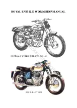
ROYAL ENFIELD WORKSHOP MANUAL 

Contents 


1956-62 "350 Bullet" and "500 Bullet", 1958--61 "350 Clipper" (including  

"Airflow" models) and Trials "Works Replica" 1958 onwards 


SECTION A14a  


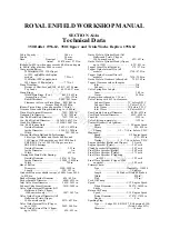
     350 DATA TECHNICAL 


SECTION A14b 


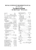
            500 DATA TECHNICAL 


SECTION C14                           SERVICE OPERATIONS WITH ENGINE IN FRAME 
 

SECTION D2                            SERVICE OPERATIONS WITH ENGINE REMOVED 
 

SECTION E1 

                                                                     GEARBOX AND CLUTCH 


SECTION F4 

                                                                                      CARBURETTER 


SECTION G1e 

                                                                                        SR1 MAGNETO 


SECTION G2k                                         GENERATOR/RECTIFIER CHARGING SET 
 

SECTION G4a 

                                                                                                  BATTERY 


SECTION G5d 

                                                                      HEAD AND TAIL LAMPS 


SECTION H5 

                                                                                                       FRAME 


SECTION J1 

                                                                                           FRONT FORK 


SECTION K6 

                                                          FRONT WHEEL (DUAL BRAKE) 


SECTION K7 

                                                 FRONT WHEEL (7” SINGLE BRAKE) 


SECTION L12 

                                                REAR WHEEL (NON-DETACHABLE) 


SECTION L13 

                                        REAR WHEEL (QUICKLY DETACHABLE) 


SECTION M2 and M4                                                                                 SPECIAL TOOLS 
 

SECTION P1 

                                                                                  AIRFLOW FAIRING


www.hitchcocksmotorcycles.com

Содержание 350 BULLET 1956

Страница 1: ... MANUAL WORKSHOP MAINTENANCE MANUAL FOR THE Royal Enfield 350 BULLET 1956 on 500 BULLET 1956 on 350 CLIPPER 1958 on Including AIRFLOW models And TRIALS WORKS REPLICA MAN7 w w w h i t c h c o c k s m o t o r c y c l e s c o m ...

Страница 2: ...NS WITH ENGINE REMOVED SECTION E1 GEARBOX AND CLUTCH SECTION F4 CARBURETTER SECTION G1e SR1 MAGNETO SECTION G2k GENERATOR RECTIFIER CHARGING SET SECTION G4a BATTERY SECTION G5d HEAD AND TAIL LAMPS SECTION H5 FRAME SECTION J1 FRONT FORK SECTION K6 FRONT WHEEL DUAL BRAKE SECTION K7 FRONT WHEEL 7 SINGLE BRAKE SECTION L12 REAR WHEEL NON DETACHABLE SECTION L13 REAR WHEEL QUICKLY DETACHABLE SECTION M2 a...

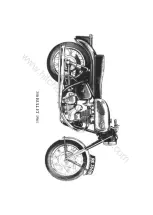
Страница 3: ...ROYAL ENFIELD WORKSHOP MANUAL 350 BULLET 1961 w w w h i t c h c o c k s m o t o r c y c l e s c o m ...

Страница 4: ...ter 3410 3405 in Valve Guide Internal Diameter All Bullets and Trials Clipper 1960 onwards only 3447 3437 in Valve Guide External Diameter All Bullets and Trials Clipper 1960 onwards only 6275 6270 in Valve Guide Internal Dia Clipper up to 1959 3452 3442 in Valve Guide External Dia Clipper up to 1959 625 623 in Guide Hole in Cylinder Head All Bullets and Trials Clipper 1960 onwards only 622 623 in...

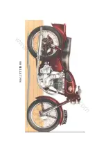
Страница 5: ...ROYAL ENFIELD WORKSHOP MANUAL 500 BULLET 1956 w w w h i t c h c o c k s m o t o r c y c l e s c o m ...

Страница 6: ...dle Dia 1959 onwards 5617 5615 in Rocker Bush Diameter 1959 onward 5627 5622 in Inlet Valve Stem Diameter 3430 3425 in Exhaust Valve Stem Diameter 3410 3405 in Valve Guide Internal Diameter 3447 3437 in Valve Guide External Diameter 6275 6270 in Guide Hole in Cylinder Head 626 625 in Tappet Stem Diameter 375 374 in Tappet Guide Internal Diameter 3760 3752 in Tappet Guide External Diameter 7510 750...

Страница 7: ...ROYAL ENFIELD WORKSHOP MANUAL w w w h i t c h c o c k s m o t o r c y c l e s c o m ...

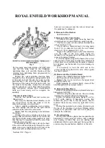
Страница 8: ... with the cam pinions and the position for correct timing is marked on the pinions by small dots Rotate the engine to top dead centre and put the exhaust or right hand cam pinion in position so that the pair of dots on it are opposite the pair of dots on the timing pinion on the crankshaft Put the inlet or left hand cam pinion in position so that the single dot on it is opposite the single dot on ...

Страница 9: ...til the piston is 1 2 7 16 in for the 350 c c Engine or 3 8 5 16 in for the 500 c c Engine before top dead centre on the compression stroke i e with both valves closed Insert a thin piece of paper between the point of the contact breaker and turn the magneto forwards or clockwise looking on the contact breaker until the paper can just be pulled out Tighten the pinion and auto advance device on to ...

Страница 10: ...with a hammer on the end of the rocker will help to ensure this See that the valve stem caps are in place After the engine has been run long enough to get thoroughly hot the tightness of the nuts should be rechecked It will be found convenient for this purpose to use a small auxiliary petrol tank while the engine is being warmed up on the stand because all the cylinder head nuts are not accessible...

Страница 11: ...ed which can easily be made The first is a piece of tube with an internal bore of not less than 7 8 in The second is a mandrel about 4 in long made from 9 16 in diameter bar with the end turned down to 11 32 in diameter for 1 2 in Support the cylinder head on the tube which fits over the collar of the valve guide Using the mandrel force the guide out of the head with a hand press or by using a ham...

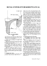
Страница 12: ... allows a smooth flow of gas without eddies If the inlet valve or its seat is pitted and requires recutting care must be taken to reproduce the correct profile as shown in Fig 6 The cylinder head should preferably be returned to the Works for the inlet valve seat to be recut but if this is not possible a special tool consisting of an arbor and cutter is available For the 350 Bullet the arbor and c...

Страница 13: ...clean oil before replacing the cover 16 Overhaul of Oil Pumps Remove the timing cover as described in subsection 1 Remove the end plates from both pumps Remove the pump discs and plungers Remove the pump spindle which can be pulled out from the front or return pump end Check the fit of the plungers in the pump disc which should have a minimum of clearance but should be able to be moved in and out ...

Страница 14: ...e type which incorporates an auto advance unit is removed by unscrewing the centre nut This will draw the pinion and auto advance unit of the shaft Coil ignition models The auto advance mechanism in this case is in the contact breaker unit and the pinion is drawn off by removing the securing nut and operating the extractor tool The Works Replica which employs magneto ignition but no auto advance m...

Страница 15: ...sprocket Remove the clutch as described in Subsection 23 Remove the primary chain tensioner Remove the rear half of the primary chaincase by taking out three socket screws Remove the grub screw locking the final drive sprocket nut Hold the sprocket and remove the nut right hand thread The sprocket can then be withdrawn 25 Pressure Relief Valve There are two pressure feeds to the big end and to the...

Страница 16: ...bolt or nut and washer Having fitted the rotor secure the adaptor ring on later models with the three cheese headed screws and shake proof washers or in the case of earlier models place the three distance pieces over the three chaincase studs The stator may then be fitted with the coil connections facing outward the leads on the inside at 12 o clock Replace the nuts and shake proof washers only fi...

Страница 17: ...ROYAL ENFIELD WORKSHOP MANUAL 350 TRIALS WORKS REPLICA 1960 61 350 BULLET 1959 w w w h i t c h c o c k s m o t o r c y c l e s c o m ...

Страница 18: ...g side ball race and the driving side outer roller race will remain in the driving side half of the crankcase The driving side inner roller race and the inner distance piece will remain on the engine shaft The flywheel assembly may be difficult to remove from the driving side of the crankcase owing to the shaft being a tight fit in the inner race of the ball bearings This is particularly likely in...

Страница 19: ...o clean the oil passages after which a new grub screw must be fitted Mount the crankshaft between centres and true up to 0005 in on either side of the shafts If the readings for the two shafts are high on opposite sides the error can be corrected by gently tapping either or both of the flywheels If the readings are high on the same side of the two shafts it is probably due to dirt or foreign matte...

Страница 20: ...n Subsection 4 Fit the inner distance piece and the rollers and cage in the driving side crankcase Lay the thrust washer on the bearing Assemble the flywheel into the bearing if necessary using the sprocket nut with suitable packing piece to draw the driving shaft through the inner race s of the ball bearing s Make sure that the crankcase face is clean and apply jointing compound to it Put the thr...

Страница 21: ...ROYAL ENFIELD WORKSHOP MANUAL 350 CLIPPER 1958 w w w h i t c h c o c k s m o t o r c y c l e s c o m ...

Страница 22: ...move the top small inspection cover and disconnect the clutch cable Remove four screws and the gearbox outer cover can then be detached Remove the gear change mechanism by taking off the two nuts securing it Remove the main shaft bearing cover which is attached by two screws Remove four cheese headed screws and hexagon bolt Remove the spring box locating plunger nut and washer Remove the main shaf...

Страница 23: ...ROYAL ENFIELD WORKSHOP MANUAL Section E1 Page 2 w w w h i t c h c o c k s m o t o r c y c l e s c o m ...

Страница 24: ...ubsection 2 but the following points should be noted If the main shaft top gear pinion and dog have been removed make sure that the dog is replaced the right way round or third and top gears can be engaged simultaneously Make sure that the trunnions on the operator fork engage with the slots in the inside operator See that the main shaft is pushed right home It may tighten in the felt washer insid...

Страница 25: ...lamping bolt in the horizontal lever and turning the lever on its spindle which is the end of the operating worm in the gearbox cover When correctly adjusted the lever should be approximately square with the cable when the clutch is fully lifted The position of the lever endwise on the worm spindle is important and it should be positioned so that it does not foul the kickstart lever 8 Adjustment o...

Страница 26: ...w and a stop which holds the throttle open a very small amount The throttle slide is cut away at the back and the shape of this cut away controls the mixture at throttle openings slightly wider than that required for slow running There is a compensating system to prevent undue enriching of the mixture with increasing engine speed this system consisting of a primary choke surrounding the upper end ...

Страница 27: ... of any parts of the carburetter Assuming that the carburetter has the standard setting to suit the particular type of engine any small adjustments occasioned by atmospheric conditions changes in quality of fuel etc can usually be covered by adjustment of the pilot air screw and raising or lowering the taper needle one notch If however the machine is used at very high altitudes or with a very rest...

Страница 28: ...ROYAL ENFIELD WORKSHOP MANUAL Section F4 Page 3 w w w h i t c h c o c k s m o t o r c y c l e s c o m ...

Страница 29: ...less dirt is present or of course the float is punctured If it is necessary to remove the jet block note that this is withdrawn from the upper end of the mixing chamber after unscrewing the jet holder Be careful not to damage the jet block when re moving or refitting it Note that the large diameter of the jet block pulls down on to a thin washer A single strand of an inner control cable is useful ...

Страница 30: ...ROYAL ENFIELD WORKSHOP MANUAL Section F4 Page 5 w w w h i t c h c o c k s m o t o r c y c l e s c o m ...

Страница 31: ...ROYAL ENFIELD WORKSHOP MANUAL 1961 350 CLIPPER 1956 350 BULLET w w w h i t c h c o c k s m o t o r c y c l e s c o m ...

Страница 32: ...l causes a high voltage to be induced in the secondary winding The body of the magneto is formed of a single casting enclosed at the contact breaker end by a moulded cover The cover is designed with the high tension cable outlet in a downward direction thus preventing the retention of moisture at the terminal connection The coil and capacitor are robustly constructed and specially treated to withs...

Страница 33: ... retaining screw and pull out the old cable Push the new cable fully home and secure by tightening the screw The pointed end of this will pierce the insulation make contact with the cable core and lock the cable in place After fitting a high tension cable a continuity test should be made between the cover electrode and plug end of the cable 3 Servicing To locate cause of misfiring or failure of ig...

Страница 34: ...m The alternator comprises two main components a stator and a rotor The stator is built up from iron laminations and carries three pairs of series connected coils insulated from the laminations The rotor has a hexagonal steel core each face of which carries a permanent magnet keyed to a laminated pole tip The pole tips are riveted circumferentially to brass side plates the assembly being cast in a...

Страница 35: ...troke of the engine does not do so on the twin owing to the fact that the distributor permits the passage of a spark only when the engine is near the firing position 5 Direct Operation Short journeys without the battery can be made with the switch in the EMG position To do this the cable normally connected to the battery negative terminal must be connected to an earthed point on the machine If lig...

Страница 36: ...miles remove the central fixing bolt and inject a small amount of clean engine oil into the hole thus exposed When the fixing bolt has been replaced and the engine run for a few minutes the oil will be forced out over the automatic advance mechanism by centrifugal force To expose the automatic timing mechanism remove the two screws in the slotted holes of the C B base plate Later Models Remove the...

Страница 37: ...ugh the metal washer and bend them back radially Screw the terminal into the pick up moulding To connect the cable to ignition coil model MA6 pass the cable through the rubber grommet push the metal clip into the end of the cable which should be cut off square insert the cable and clip into the socket in the end of the coil and slide the grommet into place to exclude water w w w h i t c h c o c k ...

Страница 38: ...ture For convenience in comparing specific gravities they are always corrected to 60 F which is adopted as a reference temperature The method of correction is as follows For every 5 F below 60 F deduct 002 from the observed reading to obtain the true specific gravity at 60 F For every 5 F above 60 F add 002 to the observed reading to obtain the true specific gravity at 60 F The temperature must be...

Страница 39: ...a low state of charge is to be expected Measure the specific gravity of the acid of each cell in turn with a hydrometer see Fig 3 The following table shows the state of charge at different values of specific gravities If the battery is discharged it must be recharged either on the motor cycle by a period of daytime running or from an external D C supply at the normal recharge rate of 1 5 amp Secti...

Страница 40: ...lenses which determine the spread and pattern of the light beams In the event of damage to either the lens or the reflector a replacement light unit must be fitted 3 Replacing the Light Unit and Bulb Slacken the securing screw at the top of the headlamp rim Remove the front rim and Light Unit assembly Withdraw the adaptor from the Light Unit by twisting it in an anti clockwise direction and pullin...

Страница 41: ...4 6 volt 6 18 watt for larger capacity machines The 3 or 6 watt filament provides the normal tail light while the 18 watt filament is illuminated on movement of the brake pedal Care must be taken that the leads to the stop tail lamp are correctly connected as the use of the 18 watt filament on the normal tail light will not only discharge the battery but could cause trouble from excessive heat aff...

Страница 42: ...ROYAL ENFIELD WORKSHOP MANUAL Section H5 Page 1 w w w h i t c h c o c k s m o t o r c y c l e s c o m ...

Страница 43: ...in See Section C paragraph 8 The procedure for all models is then as follows Remove the top pivot pin nut drive out the pivot pin then hinge the suspension unit back on the lower pivot pin After removing the lower nut the unit may be pushed off the pivot pin welded to the fork end 4 Servicing Rear Suspension Units The proprietary units fitted are sealed and servicing of the internal mechanism can ...

Страница 44: ...ROYAL ENFIELD WORKSHOP MANUAL DUAL SEAT MUDGUARD ASSEMBLY 1961 ONWARDS Fig 3 Section H5 Page 3 w w w h i t c h c o c k s m o t o r c y c l e s c o m ...

Страница 45: ...s are provided for the steering head as experience has shown that the provision of nipples at this point causes trouble through chafing and cutting of control and lighting cables If the steering head bearings are well packed they will last for several years or many thousands of miles Recommended greases are Castrolease Heavy Mobilgrease No 4 Esso Grease Energrease C I or Shell Retinax A 9 Dismantl...

Страница 46: ...oil is forced between the spring stud and the bore of the valve port forming a hydraulic damping system A compression spring is fitted inside the main tube between the upper end of the spring stud and the upper end of the main tube The lower end of the main tube and upper end of the bottom tube are protected by a cover secured to the fork crown A special fork is available for sidecar machines This...

Страница 47: ...d of the bump stroke the larger diameter taper on the oil control collar 38075 enters the main counterbore of the valve port thus forming a hydraulic cushion to prevent metal to metal contact 3 Dismantling the Fork to Replace Spring Oil Seal or Bearing Bushes Place the machine on the centre stand disconnect the front brake control and remove the front wheel and mudguard complete with stays Unscrew...

Страница 48: ...ree threads on the stud project beneath the end of the bottom tube Now fit the nut and washer and pull the stud into position by tightening the nut If necessary fit the nut first without the washer until sufficient thread is projecting to enable the washer to be fitted 6 Steering Head Races The steering head bearing consists of two deep groove thrust races each containing nineteen 1 4 in diameter ...

Страница 49: ...ffected by the oil which forms the hydraulic damping medium All that is necessary is to keep sufficient oil in the fork to ensure that the top end of the bottom spring stud is never uncovered even in the full rebound position The level of oil in the fork can be gauged by removing the top plug screw and inserting a long rod about 3 8 in diameter If slightly tilted this will ledge against the nut at...

Страница 50: ...Removal of Brake Cover Plate Assemblies Lock the brake on by pressure on the operating lever 38905 R H or 38906 L H and unscrew the cover plate nuts 31347 The right and left hand cover plate assemblies can then be withdrawn from the respective brake drums 3 Removal of Brake Shoes and Springs This is best done by unscrewing the pivot pin locknuts 28715 and the operating lever nuts 10314 after which...

Страница 51: ... it is therefore necessary for the bearings to be a tight fit in the barrel but this fit must not be so tight as to close down the outer race of the bearing and thus overload the balls The following are the manufacturing tolerances which control the fit of the bearings The figures for the bearings themselves are for SKF bearing but other manufacturers tolerances are similar Bearing o d 1 5622 1 56...

Страница 52: ...servo action the wear on the leading shoe with a floating cam housing is greater than that of the trailing shoe and in time the limit of float of the cam housing will be reached after which the brake will continue to function as a fixed cam brake with some loss of efficiency This can be restored by removing the shoes and fitting them in the opposite positions Floating cam brakes are self centering...

Страница 53: ...re Pressure The recommended pressure for the front tyre is 18lb per square inch for wheel loads up to 240lb 17 Lubrication No grease nipple is provided on later hubs due to the tendency to over grease resulting in grease finding its way past the felt seal on to the brake linings The correct method of lubrication is to pack the bearings with grease after dismantling the hub as described above Note ...

Страница 54: ...s and if requiring to be renewed should be sent for servicing 4 Removal of Brake Operating Cam To remove the operating cam unscrew the nut 10314 which secures the operating lever to the splines on the cam A sharp tap on the end of the cam spindle will now free the lever after which the cam can be withdrawn from its housing Do not try and remove the brake shoe pivot pin it is cast into the brake co...

Страница 55: ...he spindle Tightening the nuts should not have any effect on the ease with which the spindle can be turned If tightening the nuts makes the spindle hard to turn this may be taken as proof that the bearings are bottoming in the recesses in the hub barrel before they are solid against the shoulders on the spindle In this case the bearing should be removed and a thin packing shim fitted between the i...

Страница 56: ...ndard tyre is Dunlop 3 25 17 in Ribbed 350 Bullet up to 1958 350 Clipper up to 1959 500 Bullet up to 1962 use a 3 25 19 in When removing the tyre always start close to the valve and see that the edge of the cover at the other side of the wheel is pushed down into the well in the rim When replacing the tyre fit the part by the valve last also with the edge of the cover at the other side of the whee...

Страница 57: ...ROYAL ENFIELD WORKSHOP MANUAL w w w h i t c h c o c k s m o t o r c y c l e s c o m ...

Страница 58: ...and to lift the wheel clear of the ground Remove the dual seat if fitted and the detachable portion of the rear mudguard Disconnect the rear driving chain at the spring link and remove the chain from the rear wheel sprocket leaving it in position on the gearbox countershaft sprocket Unscrew the rear brake rod adjusting nut completely and depress the brake pedal so as to disengage the rod from the ...

Страница 59: ... drive gearbox lift out the felt washers and distance pieces then hit one end of the spindle with a copper hammer or mallet thus driving it out of the hub bringing one bearing with it and leaving the other in position in the hub Drive the bearing off the spindle and insert the latter once more in the hub at the end from which it was removed Now drive the spindle through the hub in the opposite dir...

Страница 60: ...ing this has already been described in Paragraph 3 dealing with the 6 in brake The method is precisely the same for the 7 in brake except that owing to the different type of return springs used it is in this case possible to remove the shoes from the pivot pin and operating cam before the latter are removed from the cover plate 10 Cush Drive The sprocket brake drum is free to rotate on the hub bar...

Страница 61: ...ered and the screws securing the cam housing correctly tightened wear on both linings should be approximately equal 13 Final Reassembly of Hub before Replacing Wheel Before replacing the felt washers which form the grease seals pack both bearings with grease Recommended greases are Castrolease Heavy Mobilgrease No 4 Esso Grease Energrease C3 or Shell Retinax A These are all medium heavy lime soap ...

Страница 62: ...are Dunlop 3 50 19 in Universal tread except on the 350 Bullet where a 3 25 19 in Universal tyre is used When removing the tyre always start close to the valve and see that the edge of the cover at the other side of the wheel is pushed down into the well in the rim When replacing the tyre fit the part by the valve last also with the edge of the cover at the other side of the wheel pushed down into...

Страница 63: ...m is drilled for a grease passage but the end of this is stopped up with a countersunk screw instead of being fitted with a grease nipple This is done to prevent excessive greasing by over enthusiastic owners If the cam is smeared with grease on assembly it should require no further attention but in case of necessity it is possible to remove the screw fit a grease nipple in its place and grease th...

Страница 64: ...it may now be removed to prevent risk of them falling out when manipulating the tyre If however these are too tight a fit in the hub to come out easily they may be left in place The main body of the wheel can now be pulled across to the right hand side of the machine thus disengaging the six driving pins from the cush drive shell and enabling the wheel to be lifted out of the machine When replacin...

Страница 65: ...nment will however be maintained if both cams are moved the same number of notches of the fork ends tilting it so as to disengage the end of the brake shoe pivot pin from the slot in the fork end When replacing the wheel make sure that the dogs on the gear in the speedometer drive gearbox are engaged with the slots in the end of the hub barrel Make sure also that the speedometer drive gearbox is c...

Страница 66: ...e complete with brake shoes as described above and unscrew the three nuts at the back of the cush drive shell after bending back the locking washers The three studs 41002 are brazed to the lockring 10097 and should be driven out of the cush drive shell each a little at a time to avoid distorting the lockring or bending the studs The sprocket brake drum can now be separated from the cush drive shel...

Страница 67: ... the pivot pin is really tight in the cover plate and put a smear of grease in the grooves of the pivot pin and on the operating face of the cam also on to the cylindrical bearing surface of the operating cam if this has been removed Fit the operating lever and trunnion 23371 on its splines in a position to suit the extent of wear on the linings and secure with the nut The range of adjustment can ...

Страница 68: ...lt central in relation to the outer faces of the distance collars 41373 and 41372 The rim should be trued as accurately as possible the maximum permissible run out both sideways and radially being plus or minus 1 32 in 17 Tyre Sizes are as follows 350 Clipper 1960 onwards 3 25 17 in 350 Bullet 1959 onwards 3 25 17 in 500 Bullet up to 1959 3 50 19 in 500 Bullet 1960 onwards 3 25 19 in When removing...

Страница 69: ...ROYAL ENFIELD WORKSHOP MANUAL w w w h i t c h c o c k s m o t o r c y c l e s c o m ...

Страница 70: ... E5414 Clutch Centre Extractor 2 SECTION D2 3 E5121 Crankshaft Extractor 4 4 E4816 Roller Race Assembly Timing Side 3 4 E4817 Bearing Assembly Driving Side 3 5 E6462 Locating Plate for Assembly of Cam Spindles 4 6 E2775 Crankshaft Pot or Jig 350 Bullet 4 6 E2774 Crankshaft Pot or Jig 500 Bullet 4 SECTION H 1 5 E5431 Frame Expander 5 SECTION J I 3 E4912 Gland Nut Grips 5 3 E5418 Lockring Spanner 5 ...

Страница 71: ...ROYAL ENFIELD WORKSHOP MANUAL Section M2 Page 2 w w w h i t c h c o c k s m o t o r c y c l e s c o m ...

Страница 72: ...ROYAL ENFIELD WORKSHOP MANUAL Section M2 Page 3 w w w h i t c h c o c k s m o t o r c y c l e s c o m ...

Страница 73: ...ROYAL ENFIELD WORKSHOP MANUAL Section M2 Page 4 w w w h i t c h c o c k s m o t o r c y c l e s c o m ...

Страница 74: ...ROYAL ENFIELD WORKSHOP MANUAL Section M2 Page 5 w w w h i t c h c o c k s m o t o r c y c l e s c o m ...

Страница 75: ...ROYAL ENFIELD WORKSHOP MANUAL Section M2 Page 6 w w w h i t c h c o c k s m o t o r c y c l e s c o m ...

Страница 76: ...ROYAL ENFIELD WORKSHOP MANUAL Section M4 Page 1 w w w h i t c h c o c k s m o t o r c y c l e s c o m ...

Страница 77: ...ROYAL ENFIELD WORKSHOP MANUAL w w w h i t c h c o c k s m o t o r c y c l e s c o m ...

Страница 78: ...nd after removing two nuts the spring washers and the bridge piece from the bottom of the speedometer it may be removed To remove the ammeter it is only necessary to take off the rubber band from the body of the ammeter after disconnecting the leads and press down the small metal tabs which will be found turned outwards The ammeter will then pull out from the top of the fairing 5 Removal of the Fr...

Страница 79: ...ROYAL ENFIELD WORKSHOP MANUAL Section P1 Page 2 w w w h i t c h c o c k s m o t o r c y c l e s c o m ...

Страница 80: ...ROYAL ENFIELD WORKSHOP MANUAL Section P1 Page 3 w w w h i t c h c o c k s m o t o r c y c l e s c o m ...

Страница 81: ...ue and white main bulb wires from the dipper switch and one green and brown pilot lamp wire through the hole in the lamp body shell Fit the body shell rubber washer between the fairing and the lamp body shell rim and line up the holes in the shell rim the washer and the fairing aperture rim Secure with the four screws and locking plates keeping the threaded plate at the bottom Connect the blue and...

Страница 82: ...FIELD AMAL HITCHCOCK S MOTORCYCLES ROSEMARY COURT OLDWICH LANE WEST CHADWICK END SOLIHULL B93 0EY ENGLAND TELEPHONE 01564 783 192 E MAIL info hitchcocksmotorcycles com WEB hitchcocksmotorcycles com w w w h i t c h c o c k s m o t o r c y c l e s c o m ...

Отзывы: