


ROYAL ENFIELD WORKSHOP MANUAL
Section L12 Page 2
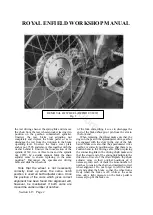
When replacing the wheel make sure that the
dogs on the speedometer drive gearbox are
engaged with the slots in the end of the hub
barrel. Make sure also that the speedometer drive
gearbox is correctly positioned so that there is no
sudden bend in the driving cable. Make sure that
the closed end of the spring link points in the
direction of travel of the chain. Replace the chain
adjuster cams in their original positions or, if
necessary, turn each of them the same number of
notches to tension the chain and maintain correct
wheel alignment. Do not forget to refit the brake
rod and adjust the brake so that the wheel turns
freely while the brake is off, while at the same
time only a small travel of the brake pedal is
necessary to put the brake on.
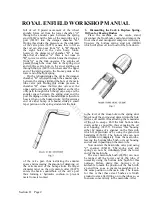
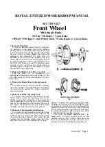
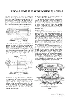
3. Removal of Brake Shoes for Replacement,
Fitting New Linings, etc.
Remove the complete wheel as described
above, then remove the left hand spindle nut,
chain adjuster and distance collar, thus permitting
the complete brake cover plate with operating
cam, pivot pin, shoes and return springs to be
lifted off the hub spindle.
In the case of the 7 in. brake fitted to the
"Meteor 700" and "500 Bullet" Models the brake
shoes can then be removed, after detaching the
return springs.
In the case of the 6 in. brake fitted to the "500
Twin" and "350 Bullet" Models, unscrew the
pivot pin locknut and the operating lever nut,
after which the assembly of the brake shoes,
return springs, pivot pin and operating cam can
be removed from the cover plate by unscrewing
the pivot pin and applying light blows with a
hammer and drift on the end of the operating
cam. The return springs can then be unhooked
from the spring posts in the brake shoes, thus
allowing the whole assembly to fall apart.
4. Replacing Brake Linings
Brake linings are supplied either in pairs ready
drilled complete with rivets, Part No. 37786BX (6
in. shoes) or 37787BX (7 in. shoes), or ready
fitted to service replacement brake shoes, Part
No. 38042 (6 in. shoes) or 38043 (7 in. shoes).
When riveting linings to shoes secure the two
centre rivets first so as to ensure that the lining
lies flat against the shoe. Standard linings are
Ferodo MR41 which are drilled to receive cheese
headed rivets.
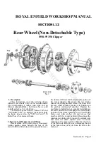
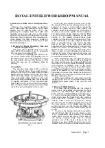
5. Removal of Hub Spindle and Bearings
To remove the hub spindle and bearings,
having already removed the brake cover plate
assembly and speedometer drive gearbox, lift out
the felt washers and distance pieces then hit one
end of the spindle with a copper hammer or mallet
thus driving it out of the hub, bringing one bearing
with it and leaving the other in position in the hub.
Drive the bearing off the spindle and insert the
latter once more in the hub at the end from which
it was removed. Now drive the spindle through the
hub in the opposite direction, when it will bring
out the remaining bearing.
6. Hub Bearings
These are deep groove single row journal ball
bearings. The lighter bearings used in the "350
Bullet" and 500 Twin hubs are 5/8 in. i/d by
1.9/16 in. o/d by 7/16 in. wide. The Skefko Part
No. is RLS5. Equivalent bearings of other makes
are Hoffmann LS7, Ransome and Marles LJ 5/8
in., Fischer LS7.
The heavier bearings used in the "Meteor 700"
and "500 Bullet" Models are 5/8 in. i/d by
1.13/16 in. o/d by 5/8 in. wide. The Skefko Part
No. is RMS5. Equivalent bearings of other makes
are Hoffmann MS7, Ransome and Marles MJ 5/8
in., Fischer MS7.
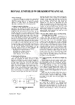
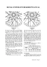
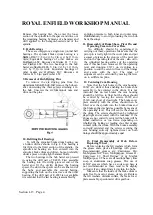
7. Fitting Limits for Bearings
The fit of the bearings in the hub barrel is
important. The bearings are locked on the spindle
between shoulders and the distance pieces, which
in turn are held up by the cover plate nuts. In
order to prevent endways pre-loading of the
bearings it is essential that there is a small clearance
between the inner edge of the outer race of the
bearing and the back of the recess in either end of
the hub barrel. To prevent any possibility of
sideways movement of the hub barrel on the
bearings it is, therefore, necessary for the bearings
to be a tight fit in the barrel but this fit must not be
so tight as to close down the outer race of the
bearing and thus overload the balls. The following
are the manufacturing tolerances which control the
fit of the bearings. The figures for the bearings
themselves are for SKF bearings but other
manufacturers tolerances are similar.
350 Bullet Meteor 700
and 500 Twin and 500Bullet
Bearing o/d 1.5622/1.5617 in. 1.8122/1.8117 in.
Housing bore 1.5620/1.5615 in. 1.8115/1.8110 in.
Bearing bore .6252/.6247 in. .6252/.6247 in.
Shaft diameter .6252/.6248 in. .6252/.6248 in.
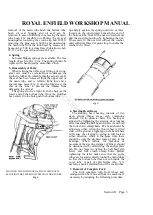
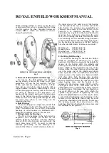
8. Refitting Ball Bearings
Note that the two ends of the spindle are not
identical. The end with the shorter plain portion
between the thread and the shoulder must be fitted
to the brake drum side of the wheel.
To refit the bearings in the hub two hollow
drifts are required, as shown in Figs. 2 and 3. One
bearing is first fitted to one end of the spindle by
means of the hollow drift; the spindle and bearing
www.hitchcocksmotorcycles.com
Содержание 350 BULLET 1956
Страница 3: ...ROYAL ENFIELD WORKSHOP MANUAL 350 BULLET 1961 w w w h i t c h c o c k s m o t o r c y c l e s c o m ...
Страница 5: ...ROYAL ENFIELD WORKSHOP MANUAL 500 BULLET 1956 w w w h i t c h c o c k s m o t o r c y c l e s c o m ...
Страница 7: ...ROYAL ENFIELD WORKSHOP MANUAL w w w h i t c h c o c k s m o t o r c y c l e s c o m ...
Страница 21: ...ROYAL ENFIELD WORKSHOP MANUAL 350 CLIPPER 1958 w w w h i t c h c o c k s m o t o r c y c l e s c o m ...
Страница 23: ...ROYAL ENFIELD WORKSHOP MANUAL Section E1 Page 2 w w w h i t c h c o c k s m o t o r c y c l e s c o m ...
Страница 28: ...ROYAL ENFIELD WORKSHOP MANUAL Section F4 Page 3 w w w h i t c h c o c k s m o t o r c y c l e s c o m ...
Страница 30: ...ROYAL ENFIELD WORKSHOP MANUAL Section F4 Page 5 w w w h i t c h c o c k s m o t o r c y c l e s c o m ...
Страница 42: ...ROYAL ENFIELD WORKSHOP MANUAL Section H5 Page 1 w w w h i t c h c o c k s m o t o r c y c l e s c o m ...
Страница 57: ...ROYAL ENFIELD WORKSHOP MANUAL w w w h i t c h c o c k s m o t o r c y c l e s c o m ...
Страница 69: ...ROYAL ENFIELD WORKSHOP MANUAL w w w h i t c h c o c k s m o t o r c y c l e s c o m ...
Страница 71: ...ROYAL ENFIELD WORKSHOP MANUAL Section M2 Page 2 w w w h i t c h c o c k s m o t o r c y c l e s c o m ...
Страница 72: ...ROYAL ENFIELD WORKSHOP MANUAL Section M2 Page 3 w w w h i t c h c o c k s m o t o r c y c l e s c o m ...
Страница 73: ...ROYAL ENFIELD WORKSHOP MANUAL Section M2 Page 4 w w w h i t c h c o c k s m o t o r c y c l e s c o m ...
Страница 74: ...ROYAL ENFIELD WORKSHOP MANUAL Section M2 Page 5 w w w h i t c h c o c k s m o t o r c y c l e s c o m ...
Страница 75: ...ROYAL ENFIELD WORKSHOP MANUAL Section M2 Page 6 w w w h i t c h c o c k s m o t o r c y c l e s c o m ...
Страница 76: ...ROYAL ENFIELD WORKSHOP MANUAL Section M4 Page 1 w w w h i t c h c o c k s m o t o r c y c l e s c o m ...
Страница 77: ...ROYAL ENFIELD WORKSHOP MANUAL w w w h i t c h c o c k s m o t o r c y c l e s c o m ...
Страница 79: ...ROYAL ENFIELD WORKSHOP MANUAL Section P1 Page 2 w w w h i t c h c o c k s m o t o r c y c l e s c o m ...
Страница 80: ...ROYAL ENFIELD WORKSHOP MANUAL Section P1 Page 3 w w w h i t c h c o c k s m o t o r c y c l e s c o m ...


