ROYAL ENFIELD WORKSHOP MANUAL
Section C14 Page 5
seats, which are of austenitic iron shrunk into the
head. Be careful not to injure the joint face which
beds down on to the head gasket.
Do not, in any circumstances, use caustic soda
or potash for the removal of carbon from
aluminium alloy.
Scrape away all carbon from the valve heads
and beneath the heads, being careful not to cause
any damage to the valve faces.
If the piston rings are removed, the grooves
can be cleaned out and new ones fitted. For
cleaning the grooves a suitable tool is a piece of
broken ring thrust into a wooden handle and filed
to a chisel point.
While the cylinder and piston are not in
position, cover the crankcase with a clean cloth to
prevent the ingress of dust and dirt of all kinds.
Do not, of course, attempt to scrape the carbon
from the piston when the mouth of the crankcase
is open.
13. Grinding in the Valves
To grind a valve, smear the seating with a little
grinding-in compound, place a light, short coil
spring over the valve stem and beneath the head,
insert the valve into its appropriate guide, press it
on to the seat using a tool with a suction cup and
with a backwards and forwards rotary motion,
grind it on to its seat. Alternatively, a tool which
pulls on the valve stem can be used. Frequently lift
the valve and move it round so that an even and
true seating is obtained. If no light spring is
available, the lifting will have to be done by hand.
Continue grinding until a bright ring is visible on
both valve and seating.
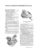
The face and seat of the exhaust valve is cut at
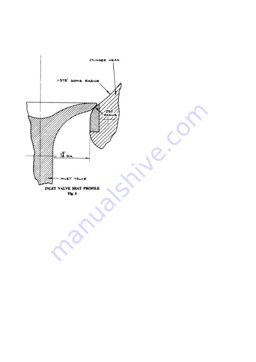
45 degrees but the profile of the inlet valve is of a
special streamlined design which eliminates
pockets and sharp edges and allows a smooth flow
of gas without eddies.
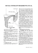
If the inlet valve or its seat is pitted and
requires recutting, care must be taken to reproduce
the correct profile as shown in Fig. 6.
The cylinder head should preferably be returned
to the Works for the inlet valve seat to be recut,
but if this is not possible a special tool consisting of
an arbor and cutter is available. For the "350
Bullet" the arbor and cutter are No. T.2053 and
T.1891; for the "500 Bullet," T.2053 and T.1892.
Great care must be exercised in using, this tool, as
it is located off the valve guide and this may be
damaged if suitable apparatus is not employed.
The inlet valve face and seat can be cut at 45
degrees in case of expediency but this may have a
deleterious effect on the performance of the
engine.
14. Reassembly after Decarbonising
Before building up the engine, see that all parts
are scrupulously clean and place them
conveniently to hand on a clean sheet of brown
paper.
When reassembling the engine, it is advisable to
fit a new paper washer between the cylinder barrel
and the crankcase.
Smear clean oil over the piston and space the
ring gaps, having replaced the rings if these have
been removed. The taper ring is marked "TOP" on
the upper face. Lower the piston over the
connecting rod and insert the gudgeon pin. Fit the
circlip securing the gudgeon pin.
If the piston ring gaps exceed 1/16 in. when the
rings are in position in the barrel, new rings should
be fitted. The correct gap for new rings is .011 in. -
015 in. The gap should be measured in the least
worn part of the cylinder, which will be found to
be the extreme top or bottom of the bore.
Oil the cylinder bore and lower the barrel over
the piston and seat it gently on the paper washer.
Tighten down the nut above the tappet chest and
replace the cylinder head and rockers as described
in Subsection 4.
www.hitchcocksmotorcycles.com
Содержание 350 BULLET 1956
Страница 3: ...ROYAL ENFIELD WORKSHOP MANUAL 350 BULLET 1961 w w w h i t c h c o c k s m o t o r c y c l e s c o m ...
Страница 5: ...ROYAL ENFIELD WORKSHOP MANUAL 500 BULLET 1956 w w w h i t c h c o c k s m o t o r c y c l e s c o m ...
Страница 7: ...ROYAL ENFIELD WORKSHOP MANUAL w w w h i t c h c o c k s m o t o r c y c l e s c o m ...
Страница 21: ...ROYAL ENFIELD WORKSHOP MANUAL 350 CLIPPER 1958 w w w h i t c h c o c k s m o t o r c y c l e s c o m ...
Страница 23: ...ROYAL ENFIELD WORKSHOP MANUAL Section E1 Page 2 w w w h i t c h c o c k s m o t o r c y c l e s c o m ...
Страница 28: ...ROYAL ENFIELD WORKSHOP MANUAL Section F4 Page 3 w w w h i t c h c o c k s m o t o r c y c l e s c o m ...
Страница 30: ...ROYAL ENFIELD WORKSHOP MANUAL Section F4 Page 5 w w w h i t c h c o c k s m o t o r c y c l e s c o m ...
Страница 42: ...ROYAL ENFIELD WORKSHOP MANUAL Section H5 Page 1 w w w h i t c h c o c k s m o t o r c y c l e s c o m ...
Страница 57: ...ROYAL ENFIELD WORKSHOP MANUAL w w w h i t c h c o c k s m o t o r c y c l e s c o m ...
Страница 69: ...ROYAL ENFIELD WORKSHOP MANUAL w w w h i t c h c o c k s m o t o r c y c l e s c o m ...
Страница 71: ...ROYAL ENFIELD WORKSHOP MANUAL Section M2 Page 2 w w w h i t c h c o c k s m o t o r c y c l e s c o m ...
Страница 72: ...ROYAL ENFIELD WORKSHOP MANUAL Section M2 Page 3 w w w h i t c h c o c k s m o t o r c y c l e s c o m ...
Страница 73: ...ROYAL ENFIELD WORKSHOP MANUAL Section M2 Page 4 w w w h i t c h c o c k s m o t o r c y c l e s c o m ...
Страница 74: ...ROYAL ENFIELD WORKSHOP MANUAL Section M2 Page 5 w w w h i t c h c o c k s m o t o r c y c l e s c o m ...
Страница 75: ...ROYAL ENFIELD WORKSHOP MANUAL Section M2 Page 6 w w w h i t c h c o c k s m o t o r c y c l e s c o m ...
Страница 76: ...ROYAL ENFIELD WORKSHOP MANUAL Section M4 Page 1 w w w h i t c h c o c k s m o t o r c y c l e s c o m ...
Страница 77: ...ROYAL ENFIELD WORKSHOP MANUAL w w w h i t c h c o c k s m o t o r c y c l e s c o m ...
Страница 79: ...ROYAL ENFIELD WORKSHOP MANUAL Section P1 Page 2 w w w h i t c h c o c k s m o t o r c y c l e s c o m ...
Страница 80: ...ROYAL ENFIELD WORKSHOP MANUAL Section P1 Page 3 w w w h i t c h c o c k s m o t o r c y c l e s c o m ...


